Wk06: 2016/03/02
ELECTRONICS DESIGN (WEEK 1 OF 2)
0. Assignments for week6
The assignments for week6 were as below;
- Redraw the echo hello-world board
- add at least a button and LED with current-limiting resistor
- (or design your own)
1. Redraw and make the echo hello-world board
This week, we redrew and made echo hello-world board as below.
Draw the Schematic
First, we install EAGLE, which is open source software for designing circuit board. Using EAGLE, we drew the schematic of echo hello-world board as below.
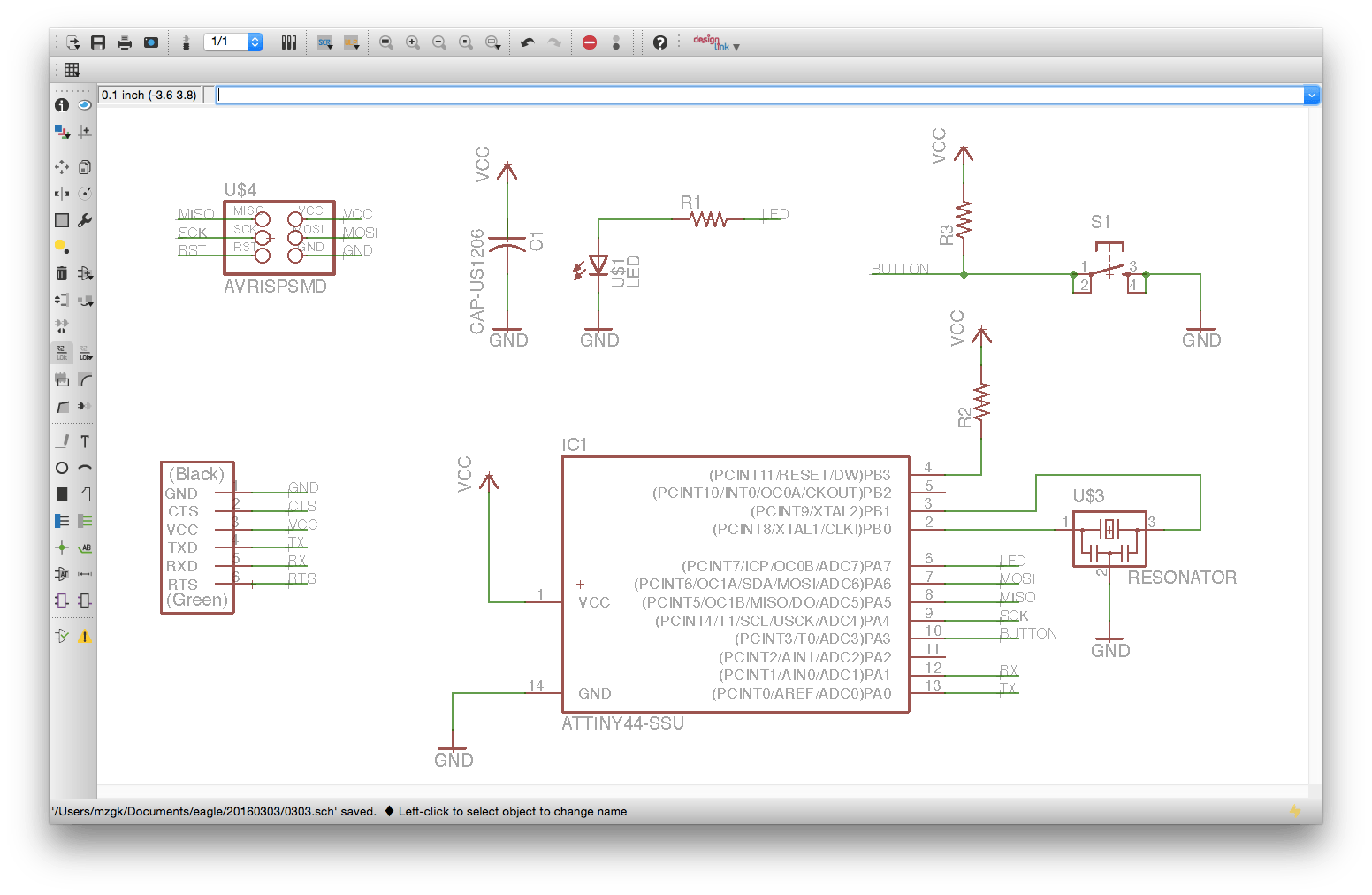
Schematic of hello-world board
And the table below is the inventory list for hello-world board. We downloaded fab.lbr from our tutorial site, and used the parts to drow the schematic above.
Bill of Hello World Board
| Part | Category | Value | Package |
|---|---|---|---|
| IC1 | microcontroller | - | ATTINY44A |
| R1/R3 | Resistor | 10 Kilo-Ohm | 1206 |
| R2 | Resistor | 499 Ohm | 1206 |
| C1 | Capacitor | - | CAP-US1206 |
| L1 | LED | - | 1206(Green) |
| S1 | Button | - | 6MM_SWITCH |
| JP1 | FTDI header | - | FTDI |
| U$3 | Resonator | 20MHz | |
| U$4 | 6-pin programming header | - | AVRISPMD |
Draw the Board
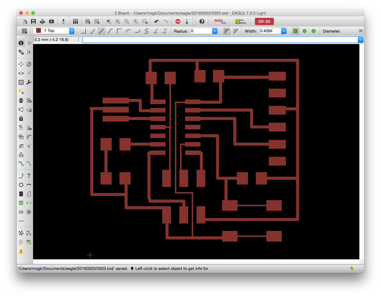
Next, we switched the drawing board mode as below. The parts which we drew and put on the shcematic was automatically connected with each other and shown on the board.
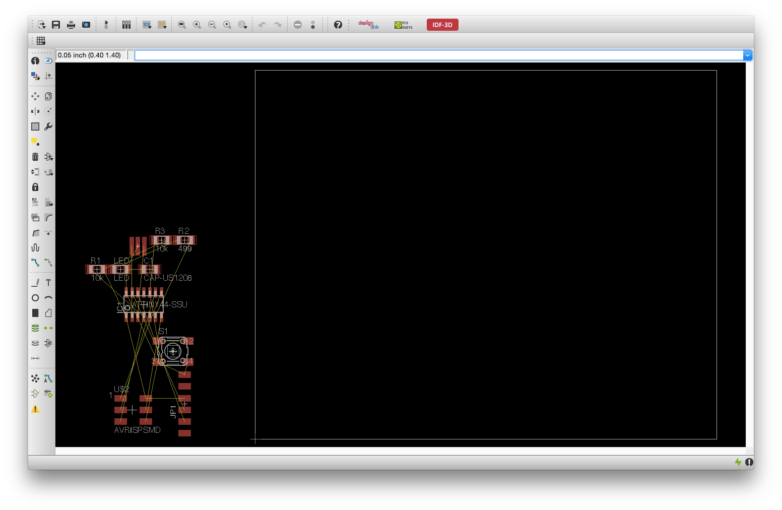
Board View on Eagle
Next, we adjust the position of each parts and make route connecting each parts, and the board below is my version 1 of hello-world board.
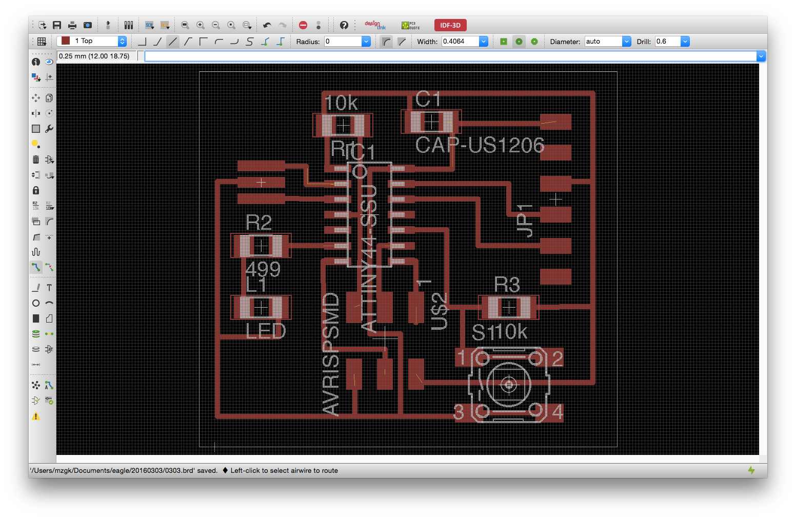
Hello-world Board version 1
After connecting the routes, we have to debug the circuit. There are several methods to debug on EAGLE as below.
- Show object: you can check connection between parts
- Calculate shortest airwires: you can see airwires
- Show errors: you can check erros ditected automatically
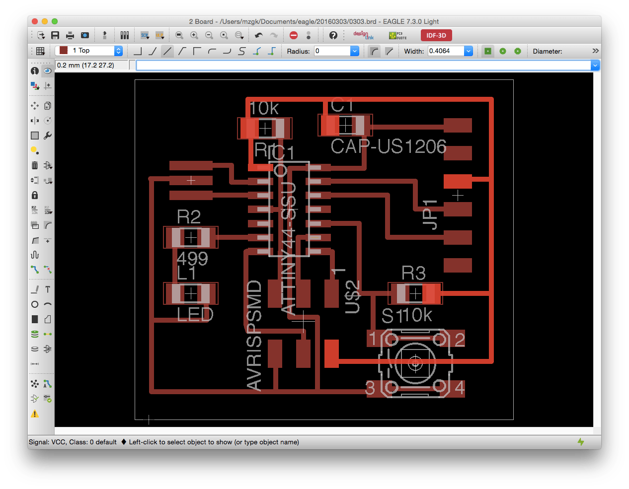
Debugging
After debugging, we can export png file from export menu. In this board, the settings should be MONOCHROME and 500 DPI.
Cutting blueprint
Draw the Board
Next, we modify the image on GIMP, which is free software enable us editing raster image. I added the edge and some characters as below. The route which had to be connected wes not connected as below.
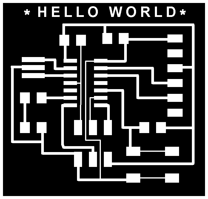
Hello-world Board version 1
Cutting by Milling machine
Then I entered into cutting on CNC milling machine, however, I made several mistakes. Generally I could did my assignments smoothly, the main bottleneck was this milling part.
First mistake was regarding the seting of Modela. Though I set 1.1 as error, it was not enough that I could not cut separately on the conrner of the board as below.
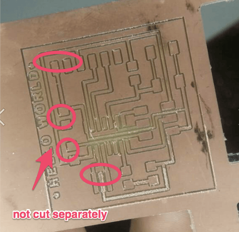
Not cut separately
Then I set 2 as offset, however, the next big mistake has occured. I set the width of route under 4mm on designing by EAGLE, so the machine cannot cutted clearly the routes on the board.
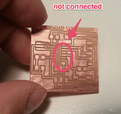
Mistaken board
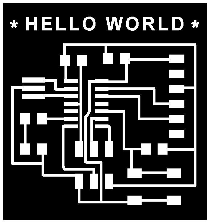
Then, I went back to EAGLE, and adjusted the width of every route. The png images below are the version 2 of hello-world board.
 |
 |
hello-world board version 2
Then finally I successfuly cut the board as below. There were several rough parts, so I used sand paper to flatten the surfase.
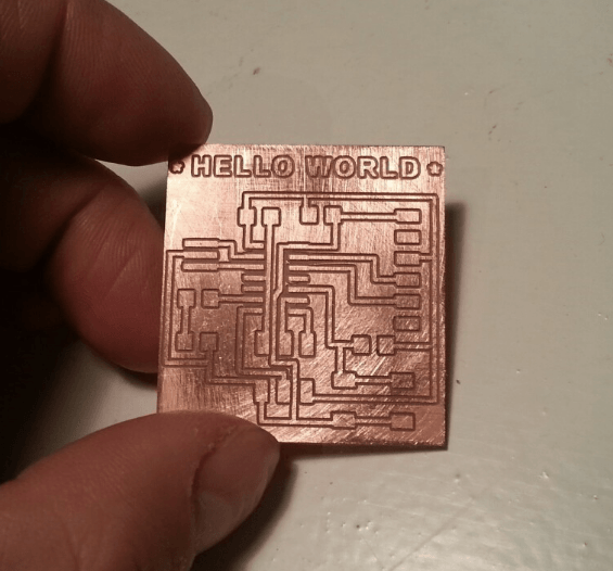
hello-world board
Solderling
Next, I soldered the components to the board I cut. Though I felt it diffucult to solder the resonator as first, generally I was able to finish the task without big problems. After soldering, I debuged and check the operation by my laptop, then I finished my assignments.
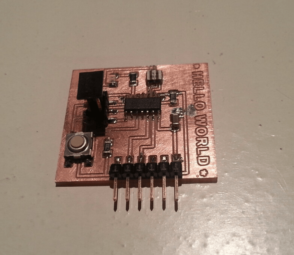
hello-world board
Outline of this page
1. Redraw and make the echo hello-world board
Download output of Wk6
Here are my output files for Wk6:
- 20160303_hello_world.PNG
- 20160303_hello_world_edge.PNG
- 20160303_hello_world.SCH
- 20160303_hello_world.BRD
- 20160303_hello_world.XCF
Lecture Material for Wk6
Lecture Note
Tools
Learning Support
- Introduction to EAGLE
You can learn how to make hello world board - Why did we put a 20MHz crystal on the Hello FTDI?
- Free simulation tools from MITx
(Basic Tutorial)
(Video Tutorial)
- Tutorial 1 for Eagle: Schematic Design
- Tutorial 2 for Eagle: Printed Circuit Board Layout
- All about learning: EAGLE Tutorial
Videos of Wk6
Here you can find this weeks's lectures on VIMEO:
(2016.03.02)
(2016.03.10)
Checklist for Wk6
Assignments:
- Redraw the echo hello-world board
- add at least a button and LED with current-limiting resistor
- (or design your own)
Learning outcomes:
- Select and use software for circuit board design
- Demonstrate workflows used in circuit board design
Have you:
- Shown your process using words/images/screenshots
- Explained problems and how you fixed them
- Done fabbercise today
- Included original design files (Eagle, KiCad, Inkscape, .cad - whatever)