Embedded programming
Theme and lecture of the week: Embedded programming
Tasks done for this week:
- Read a microcontroller data sheet, namely the data sheet of the ATMEL Tiny 24/44/84 (238 pages)
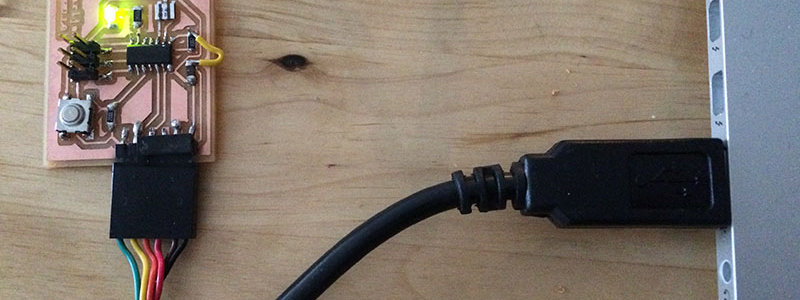
- Programmed my Hello echo board to do something (controlled blinking light, set up communication with my computer through FTDI cable connection,...)
- Exlored different programming languages and environments, namely Arduino IDE
Controlling my board
In order to program my Hello Echo board with the fabISP to do something, some steps needed to be done first:
- Install Arduino IDE
- Download the ATtiny files support for the board to be visible in the 'Tools > Board' list in the Arduino environment
- Install FTDI drivers and get FTDI cable for the serial communication
As I had previously experienced issues with older Arduino IDE environments in combination with the more recent Arduino UNO board, this time I downloaded the latest Arduino IDE (1.6.8) so it would work fine. The ATtiny is Arduino IDE compatible. However, you need to install the ATtiny files first, so that the Arduino application knows how to talk to the ATtiny (see this tutorial). After installing the files, you will see the ATtiny in your boards list. Then, you pick these settings in the Arduino IDE environment:
- Tools>Boards: ATtiny
- Tools>Clock: 20MHz
- Tools>Processor: ATtiny44
- Tools>Programmer: USBtinyISP
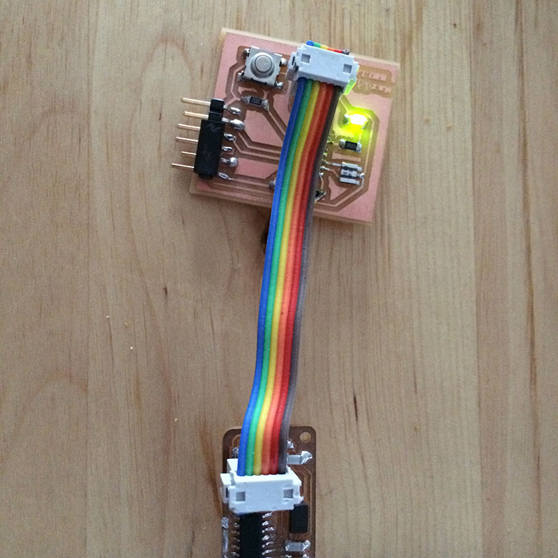
Also, make sure that the cable from the ATtinyISP is rightly connected with your board (look at the Miso in the schematic design). After that, I was able to burn the bootloader (Tools> Burn Bootloader).
What is a bootloader? "Microcontrollers are usually programmed through a programmer unless you have a piece of firmware in your microcontroller that allows installing new firmware using an external programmer. This is called a bootloader."
Then, I was ready for the real fun: uploading sketches (Arduino code) to my board. The first one was the blinky sketch (in Examples>Basics>Blink). Looking at my board schematics and the ATtiny documentation, I changed the code so to match the right pin that the LED is attached to (7 in my case).
From data sheet to working result (with public transport)
To know more about the pin configuration, the microcontroller sheet comes in handy, which goes into great detail of the functioning of Atmel's ATtiny (238 pages, and explains its memory, register, ...).
What is a ATtiny? The ATtiny is a RISK (Reduced Instruction Set Computing) microcontroller. It is not a microprocessor, such as the Pentium in PC's (see also this link for understanding the difference between microcontrollers and microprocessors), and uses a modified Harvard architecture, in which program and data are stored in separate physical memory systems that appear in different address spaces, but has the ability to read data items from program memory using special instructions.
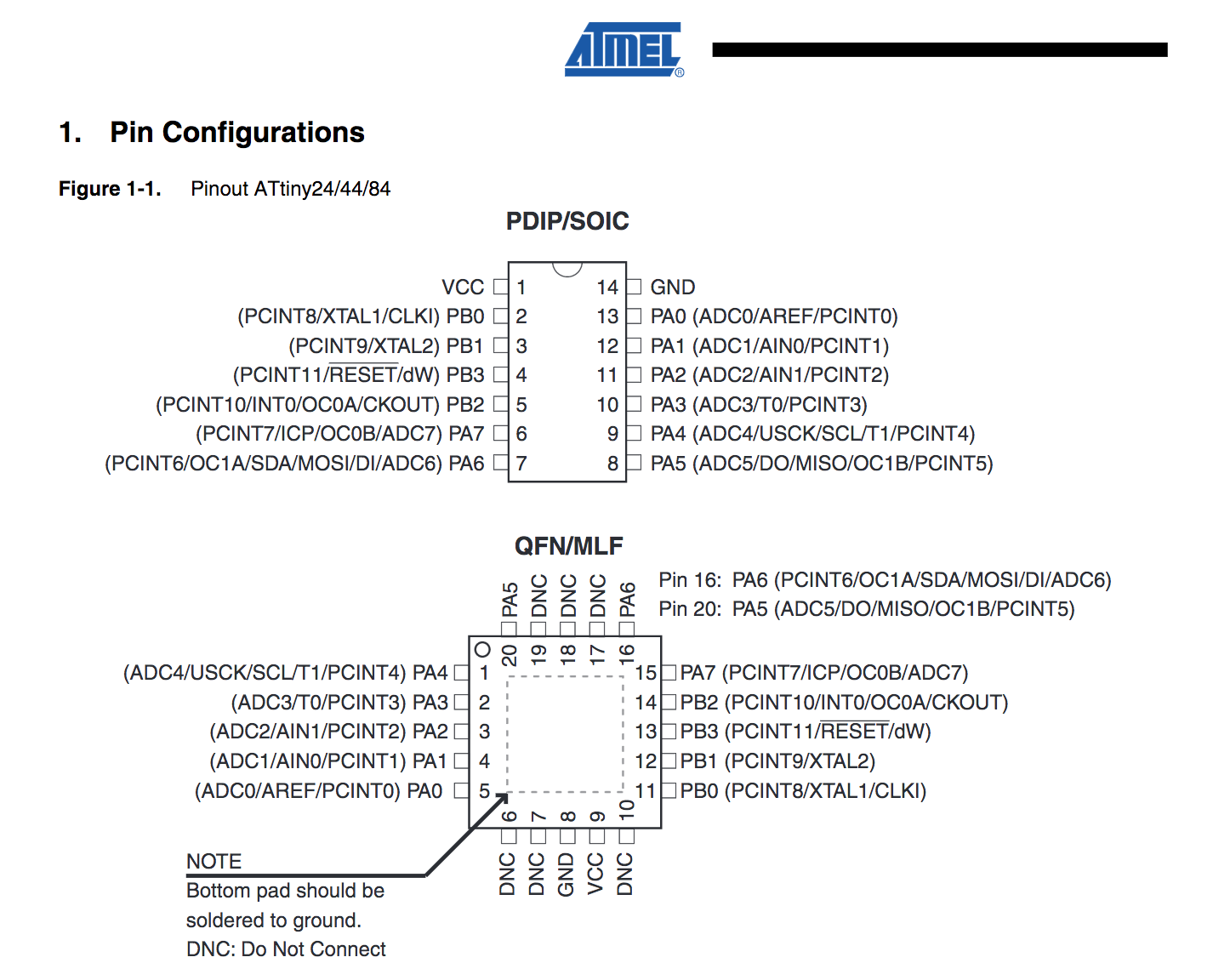 The datasheet comes with a lot of abbreviations. I unravelled some important ones:
- GND: Ground
- VCC: Voltage from a power supply
- B-port: pin 0-3 > four pins
- A-port: pin 0-7> eight pins
- Miso: Master Input Slave Output
- Mosi: Master Output Slave Input
- ADC: Analog Digital Converter
- USI: Universal Serial Interface
- AREF: External Analog Reference
- XTal: Chrystal oscillator input
- CKout: Clock output
- Reset: reset
The datasheet(s) information is not only useful for knowing about the pin outs (for rightly connecting and adressing the component), but also useful for understanding its infrastructure, clock speed, memory limitations, the power requirements and controlling output devices (see also 'mind the data sheet' in the ouput devices week). The main difference between the ATMEL Tiny 24, 44 or 84 in the documentation is the memory, which is generally not a lot. More effective memory and control are reasons why one would choose for programming in Assembly and C instead of Arduino IDE. On the other hand, Arduino IDE comes with a lot of handy libraries, example scripts and is basically also C. While Assembly may only be for the brave and those who want to control their own car, I have always been a big fan of visual control and public transport. Thus, I further experimented with coding in Arduino IDE. Although I had made LEDs blinking in the past (using breadboards, conductive paint, ...), used different programming languages (JAVA, C, ISIS, PYTHON, Prolog, Assembly...) and microcontrollers before (PIC during the iBand project: a wearable device for handshake-augmented interpersonal information exchange), it was the first time I was able to control my own produced ATtiny board, which was a nice result.
 Files
Files
- Button with funky LED control (blinking all the time, light stays on when pressed)
- Sketch for Serial communication
Tips
- Change the speed of the blinking light: simply adjust the 'delay' in the code
- More Arduino know how: Arduino cookbook
- Info on Arduino interfacing with other software and languages
- The USB programmer and FTDI cable should not be connected at the same time
- Make sure to properly solder the FTDI connection on the board (it gets used a lot and pins should not move)
- Do not lose the tiny screw of the end mill, if you want to produce more boards... (but do not worry too much; there should be more)
- If you mill the Arduino like Fabkit (instructions found here), make sure to check/invert the Drill .png file (using 1/32 end mill), so to mill the right parts and the holes will not turn out too big.
What more?
Although my FTDI cable connection worked in the end (with the latest Arduino software and Mac OS), there have been issues reported with maintaining a stable connection with El Capitan > thus needs more investigation.


