For this week's lesson I decided to use the Arduino IDE for windows to write and install my code from the FabISP. The Arduino IDE is designed to work with the arduino boards, but I find that it works just fine with home-made boards when you have the boards installed. The Arduino IDE is simple to install and can be found here. If you try programming first like I did, you will discover that the IDE won't recognize your FabISP. For it to recognize it, you need to install the drivers.
The first thing you need to do is to install the windows drivers for the USBTiny programmer. Adafruit supplies a similar board on it's website, and has the drivers avalible. The drivers can be found here. Download the installer and click through the installation.Your FabISP should now be recognized by the OS and the Arduino IDE.
The IDE does not support programming to an ATTiny natively, but thankfully humans exist that are willing to add them to the IDE's board manager. I found how to install the ATTiny boards and the files to do it on the HighLowTech website (the instructions can be found here). Note that my instructions for installing the board closely follows the steps found in the image below (and the website), since those are the ones I followed.
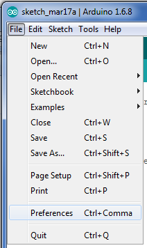
To install the board, you first need to open the IDE's preferences. The preferences are found at File>Preferences. Alternatively, you can use the shortcut Ctrl+Comma.
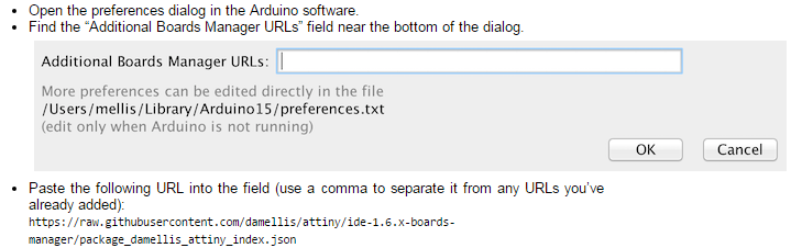
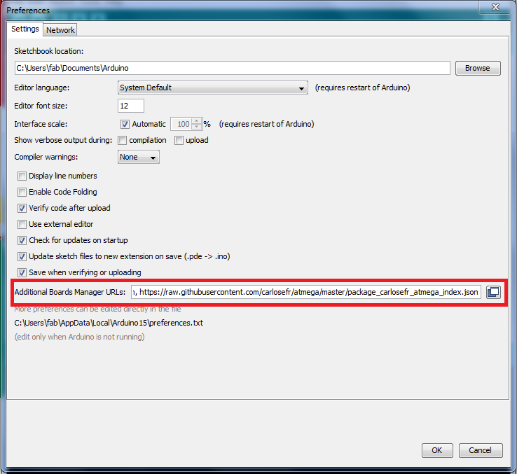
In the Preferences window, you will see a text box labeled "Additional Boards Manager URLs." In that text box, copy and pase (or type if you prefer) the following link:
https://raw.githubusercontent.com/damellis/attiny/ide-1.6.x-boards-manager/package_damellis_attiny_index.jsonIn the future, you can also put other links in there, seperated by commas, to expand the range of boards and processors you can program.
Now navigate to the boards manager, found under Tools>Board:"[Whatever]">Boards Manager... The name of the board will differ from person to person depending on which board you used last. Note that the boards manager begins installing stuff (the board package) when you enter it.
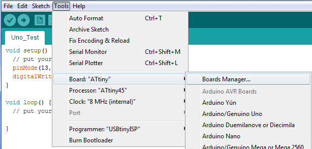
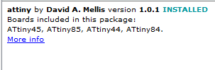
In the boards manager scroll to the very bottom. There you will find the board package (I doubt that's what it's called but I never found a proper name for it). Click on the tile to reveal the version selector and install button. Make sure you are using the latest version (I used version 1.0.1, but the future happens) and click the install button. You can now program the ATTiny with the Arduino IDE.
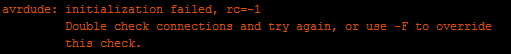
First you will want to install the bootloader. This is where I ran into my first major problem: the rather common rc=-1. The IDE was complaining about bad connections after an attempted initialization. It offered me an option to override the check, but clearly there was a problem.
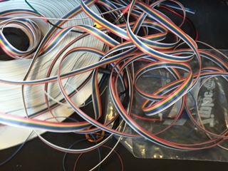
I did a google search and Adafruit gave me some answers. The first thing the website said could be the problem was a bad cable, so I made a new one to make sure the cable I was using wasn't shorting. I first dug through the mound of ribbon cable spaghetti in our wire drawer for the end of the ribbon cable.
I also checked out Fiore Basile's Page to see what his process was (at the request of Wendy Neale). While doing that, I read that He had the same problem that I did. However, his problem lay in the resonator, and my design didn't have one.
I then cut the length I thought I needed plus some extra and grabbed some 6 pin sockets. The ribbon cable has 9 wires (Why 9? 10 is a much nicer number) and I only needed 6, so I pulled the rest away. I kept the 3 remaining wires, since they might make good PWM cables. I then inserted the cable into the socket so that the brown wire (were the wires color coded with similar colors to resistors?) was on the far right with the cable facing me, with the key facing away. I then clamped the socket using a wrench (we don't have proper tools here) making sure to be gentle, or I will break the clip.
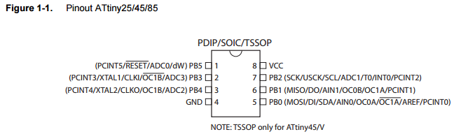
I did the same thing with the ISP end, but this time I had the key facing towards me, with the brown wire on the left. I now had a working ISP cable, but the rc=-1 problem still persisted. I then moved onto the next item on the list: power to the target device. When Fiore Basile had the same problem as I did in 2014, and this was the first thing he tried. I checked the datasheet to find the Vcc and GND pins on the Tiny45, and the voltage range that they should be at.
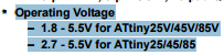
I pulled out a multimeter and set it to voltage mode. I measured the volatge across the Vcc pin and GND pin on both the device's ISP header and the chip, to check supplyfrom the ISP and the continuity of the traces. Both measured 5V, as the datasheet said they should. I then Checked the continuity of all the ISP traces on both boards, as reccomended by the Adafruit website. They all checked out, and the problem still persisted, since nothing changed.
I went home early (my dad couldn't pick me up at the usual time) and decided that I would do some testing with a board I knew worked: my Arduino Mega 2650 (yes I know that's cheating, but I wanted practice). I wrote some test code that would turn a blue LED on.
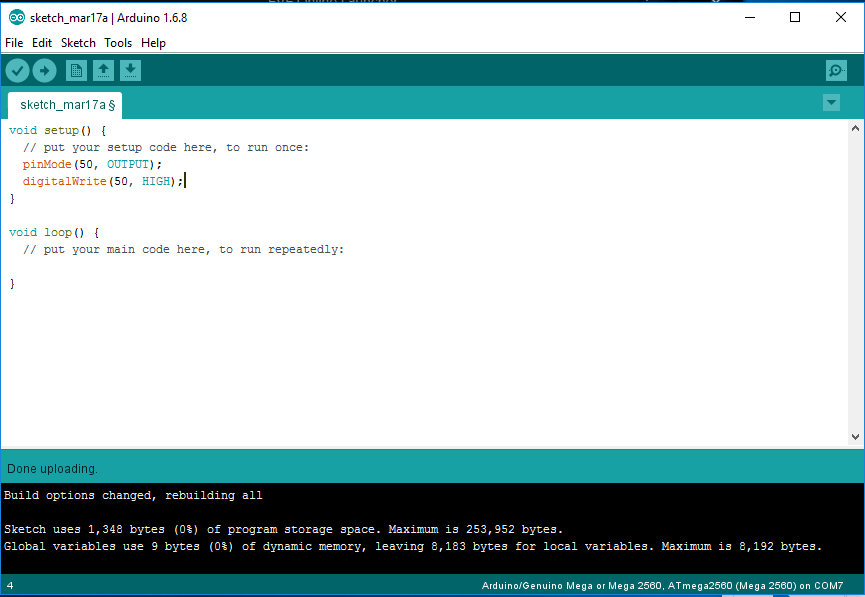 I uploaded the code
over USB, since I left my ISP at the lab. The code uploaded flawlessly and worked flawlessly. This should have been the first sign that the problem was with the ISP, but I ignored it and continued beliving that the problem llied in the board I designed.
I uploaded the code
over USB, since I left my ISP at the lab. The code uploaded flawlessly and worked flawlessly. This should have been the first sign that the problem was with the ISP, but I ignored it and continued beliving that the problem llied in the board I designed.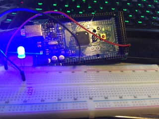
When I returned the next day, I remembered that I needed to remove a 0 ohm jumper after programming the FabISP. I then checked the board to see if it was still there. It was.
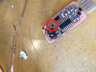
I removed the jumper with the hot air station and cleaned up the pads with some solder wick (looks are important). I then tried loading the bootloader with the newly repaired ISP. It worked like a charm.
I then moved onto programming the board. I want the board to light an LED when I push a button. I first opened up the Arduino IDE and wrote some basic code to do what I intended.
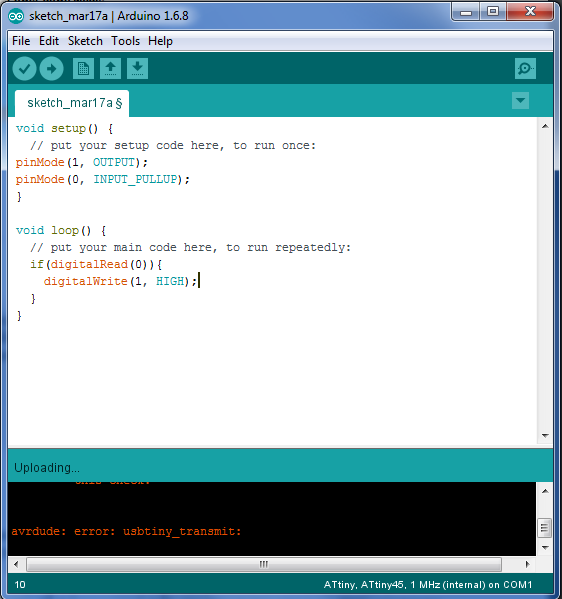
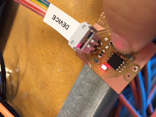
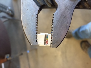
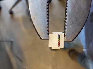
I saved the sketch and attempted to load it onto the ATTiny. At first it spit out some verification errors (different every time too) but after a few tries the IDE cooperated and installed the code. Nothing happened until I remembered /i needed to switch some jumpers from program to usage. While doing that this happened (the photo also shows the jumpers in the programming position):
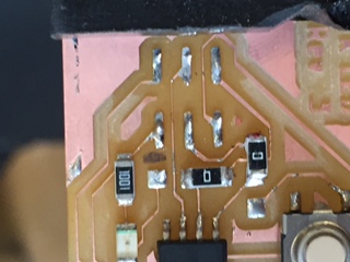
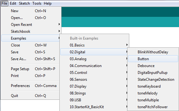
I kinda needed that ISP header so I reattached it and fixed the jumpers. When I plugged it in the LED stayed on. Nothing happened when I pressed the button either, so I needed to fix my code. I remembered that I needed an else statement to reset the LED, and added one. I also looked at an example at the reccomendation of Steven Fett. The examples can be found under File>Examples. I used te button example.
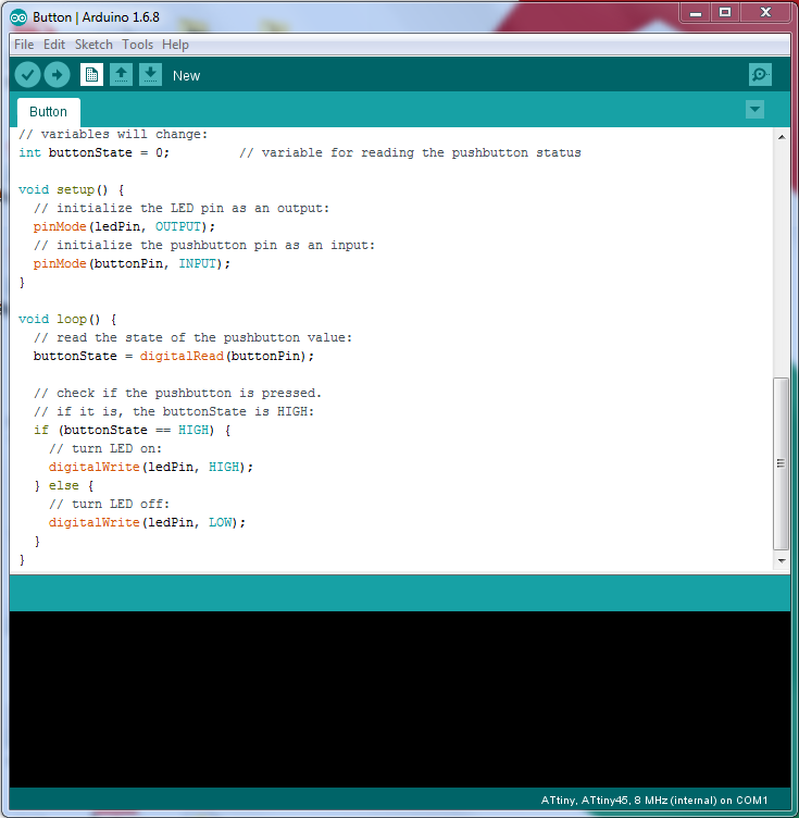
I used the syntax from that program, realizing that I should use an integer intead of a boolean. I also added some variables to make the code seem more readable.
I uploaded that and the LED stayed on when the button was pressed, so still not what I wanted, but it was closer.
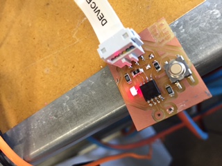
I then remembered that I had the button hooked to ground, not Vcc, so I changed the HIGH in the if statement to a LOW. this fixed the problem and now it works perfectly.