Steven Fett
Fab Academy 2016
Input Devices
Measure something: add a sensor to a microcontroller board that you have designed and read it.
3D Molding and Casting
Design a 3D mold, machine it, and cast parts from it.
Input Devices
In order to keep this documentation on track with the specific differences that happened this week I will not be covering EAGLE or Mill operation. For information on my processes please visit:
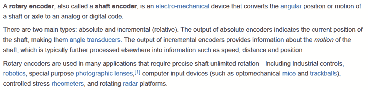
During this week we will be building an electronic board that will interface in someway with a sensor. I've decided to start with a rotary encoder.

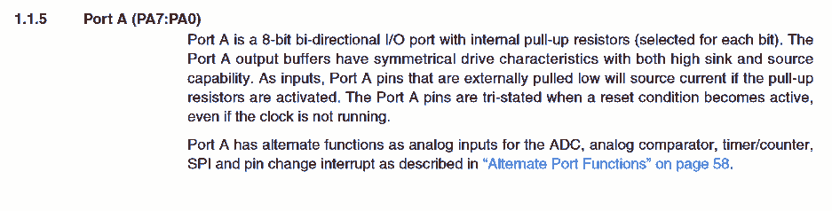
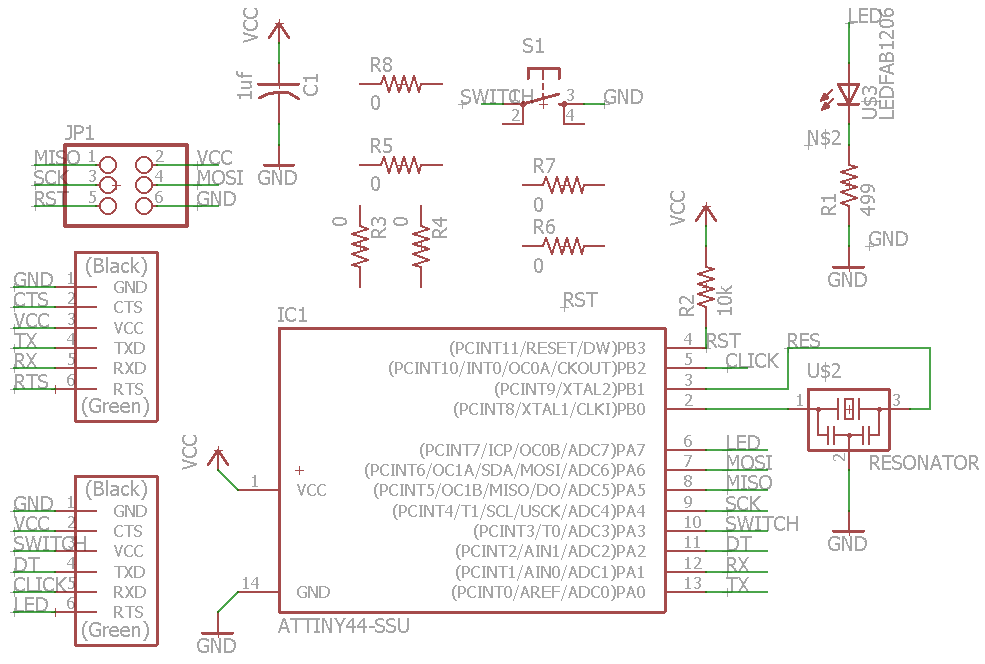
After referencing my last board, I decided to use the Hello World board again, but use up a few extra pins that we had left over. I added an additional FTDI component to my drawing and began checking the data sheet for the Pins I'll be using
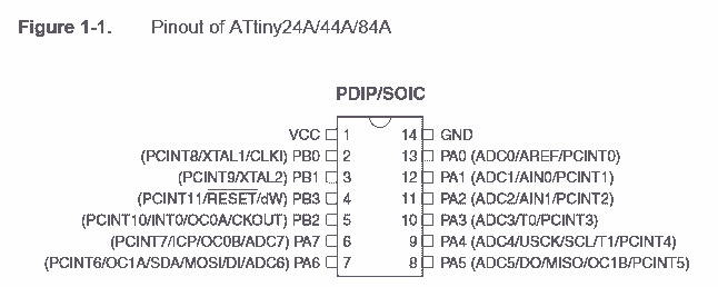
If I left the Button and LED pins on the board I had two pins open on my board; Pin 5 (PB2), and Pin 11 (PA2).
Pin PA2:
Pin PB2:
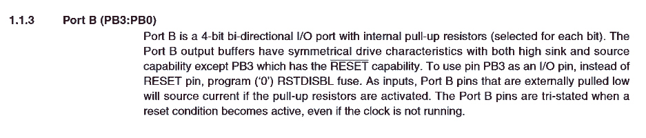
Both available pins are listed as ADC pins, they will run both analogue and digital. one being 4 bit communication and the other being 8 bit communication.
Lets take a look at our sensor and see what requirements we will need.
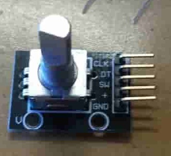
The Pin out reads from top to bottom:
CLK ,DT ,SW ,+ ,GND
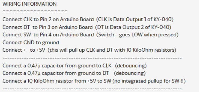
Since I already have VCC GND and SWITCH on my board I will use those existing portions and add CLK and DT.
I have an extra pin left on my additional 6 pin header I'm adding. I think I'll wire my led output up to it for use later. I'll throw a couple of Zero Ohm resistors onto the board as I may need them shortly
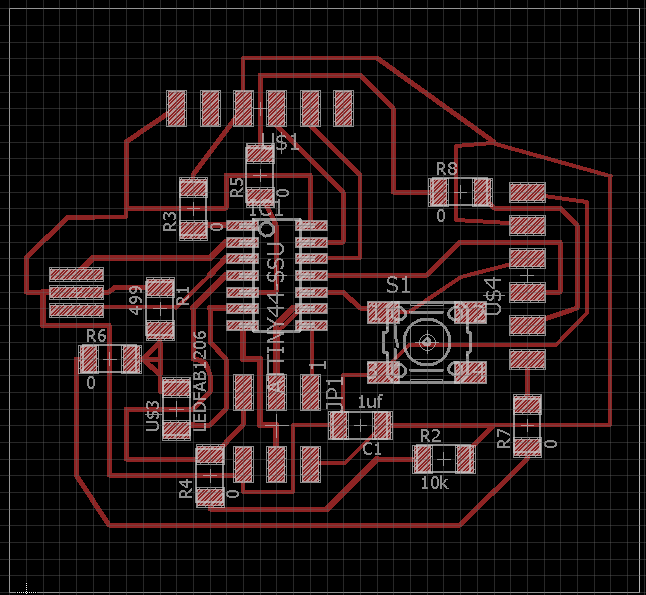
Time to layout the board.
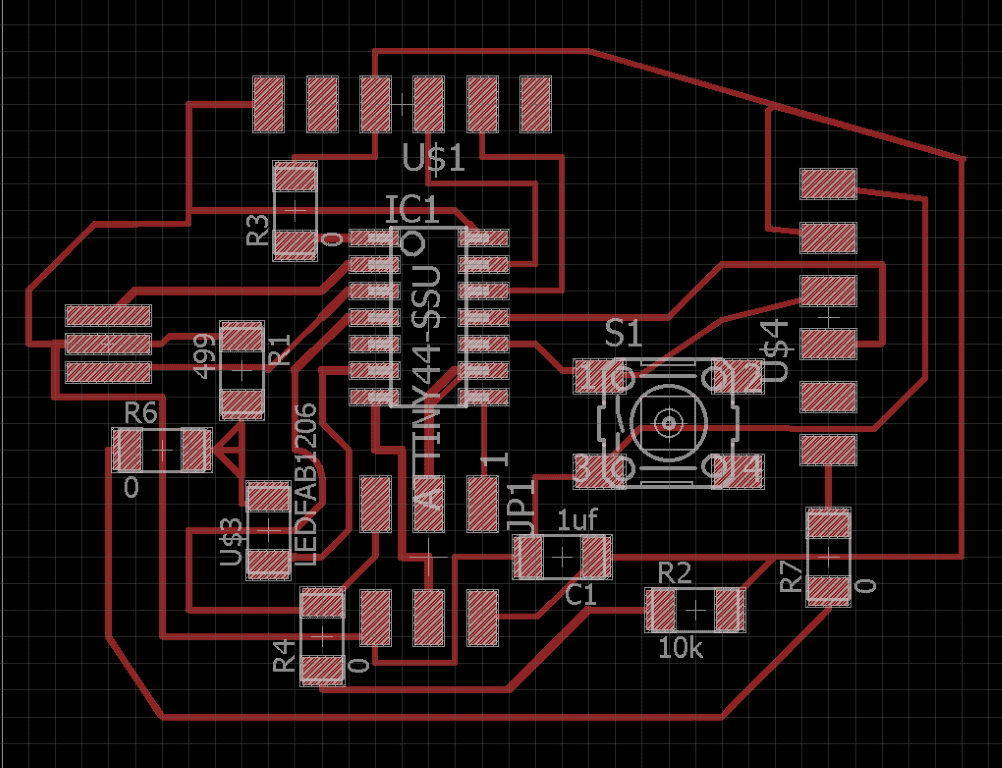
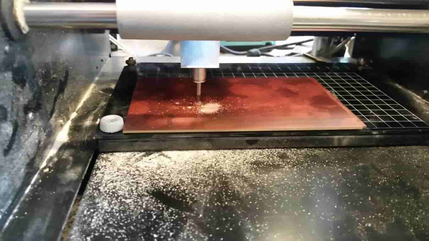
Everything looks good here. Lets generate our Board Image and take it over to the Modela.
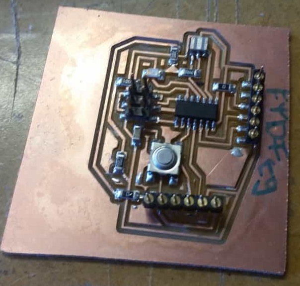
After soldering the components at the re-flow station it is time to program the board.
When programming the board I get a couple of errors in the Arduino IDE
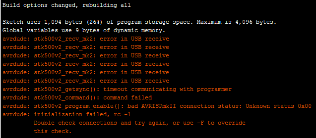
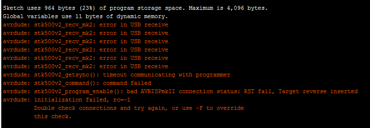
RST Fail. I think I need to troubleshoot my board some more.
My RST Net was broken and so was my CLICK Net.
Updated Sketch and Board Layout.
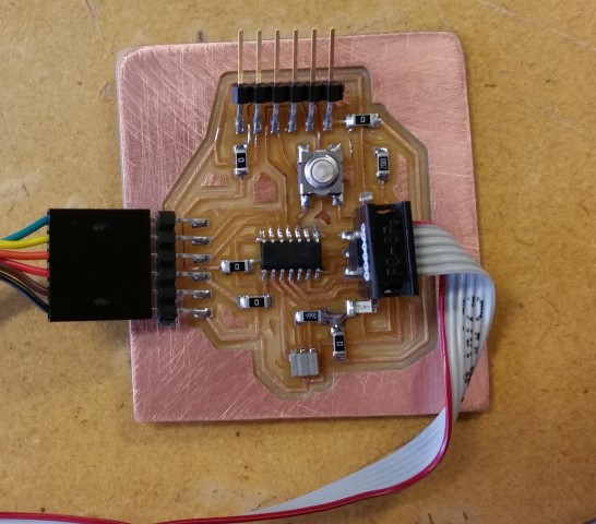
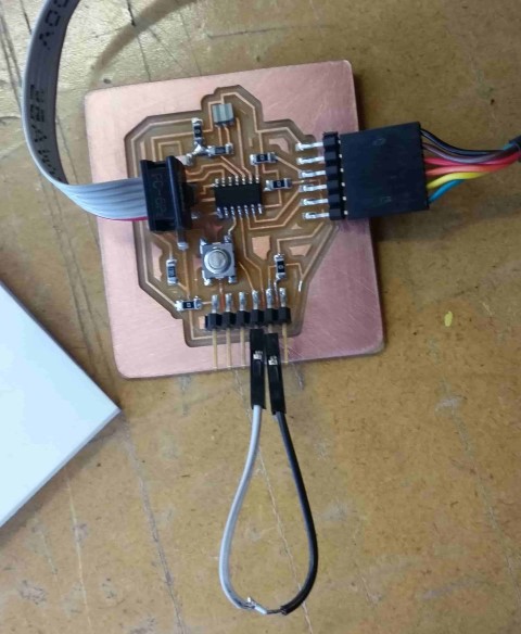
I've rebuilt my board again, this time placing the headers, buttons, and zero ohm resistors first. I added the Resonator and the IC last to be certain they are not getting cooked during the re-flow process.
Running my original blink script from a few weeks ago I was running into an issue where the board would read the proximity of my hand as a button input. Ki Fredeen pointed out that I should use INPUT_PULLUP when declaring my button pin. From what I understood this will use an internal resistor on the IC to lower the sensitivity of the circuit.
After troubleshooting the strange behavior of my board I referenced Emma Pareschi. Emma used a similar board to which I am using. She had used her Hello World Board and was able to read the on board button as input across serial. When running her script I double checked that all of her pin call-outs were the same as my board. When running the serial monitor I got scrolling space characters. when franticly pressing the button I would occasionally get an odd ASCII character.
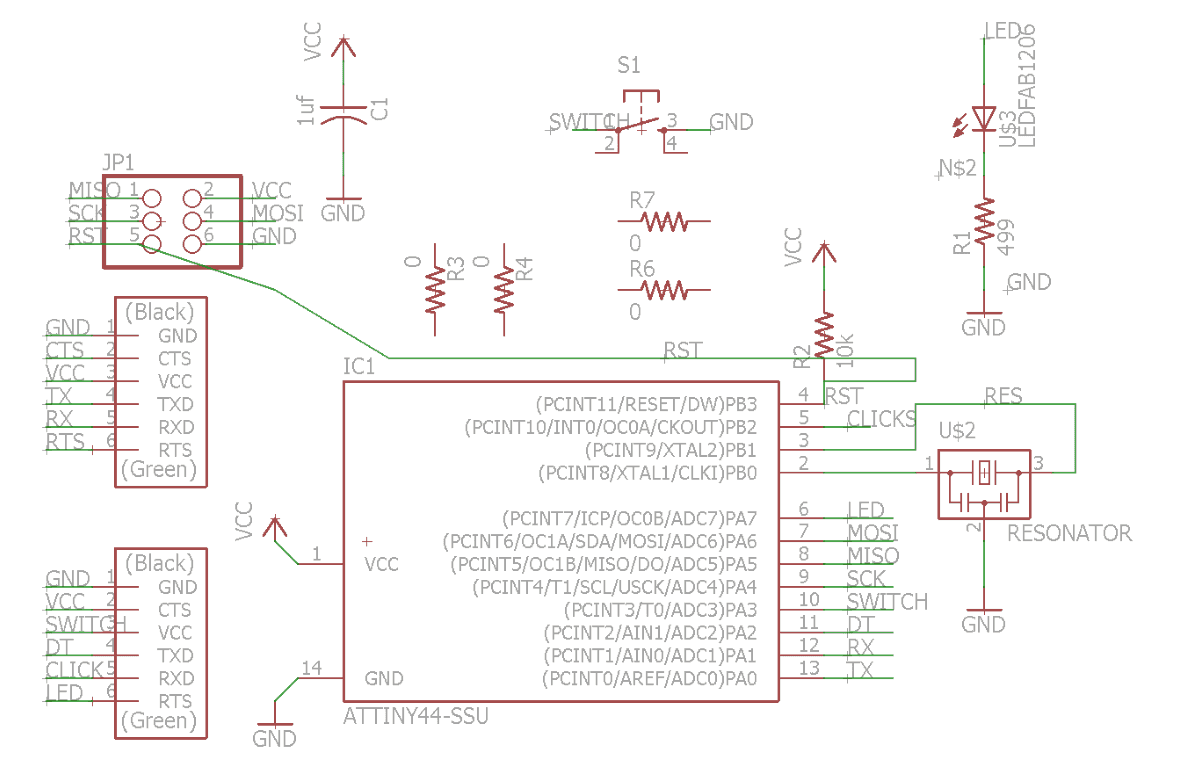
With Help from Craig Hoburn I was able to identify that I needed a physical pullup-pulldown resistor.
He sent me this Diagram.
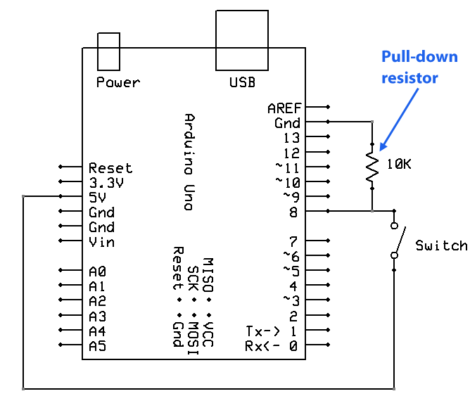
After adding a 10k resistor to my externally wired pins (VCC and Switch). I burnt my bootloader and began testing my Button and Serial Output.
IT WORKS!
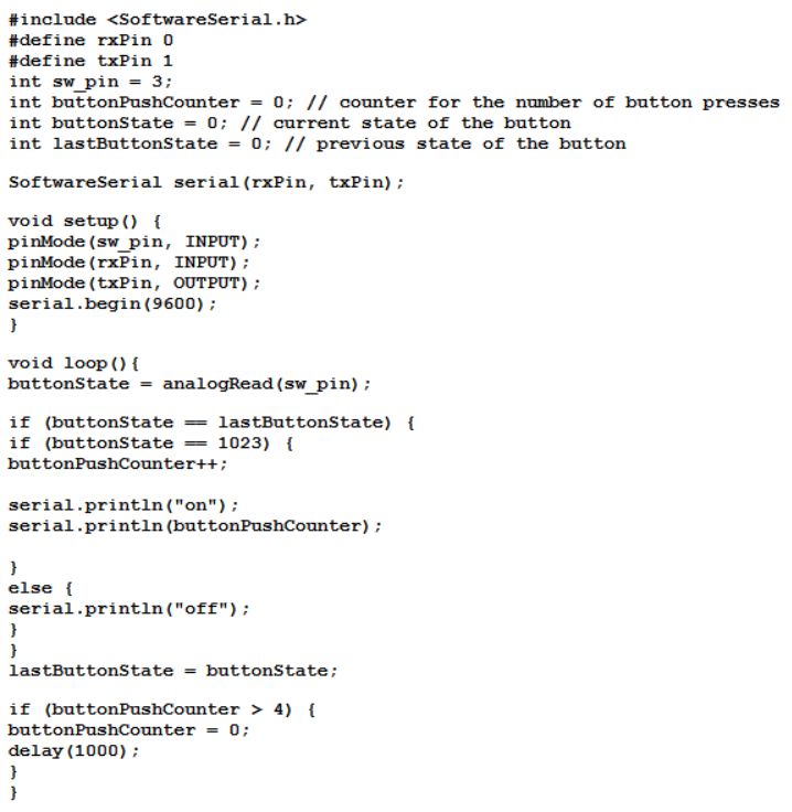
Let's analyze the code so as we know what the heck is going on.
3D Molding and Casting
Bolo Tie

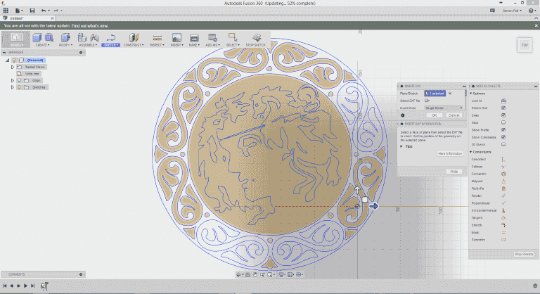
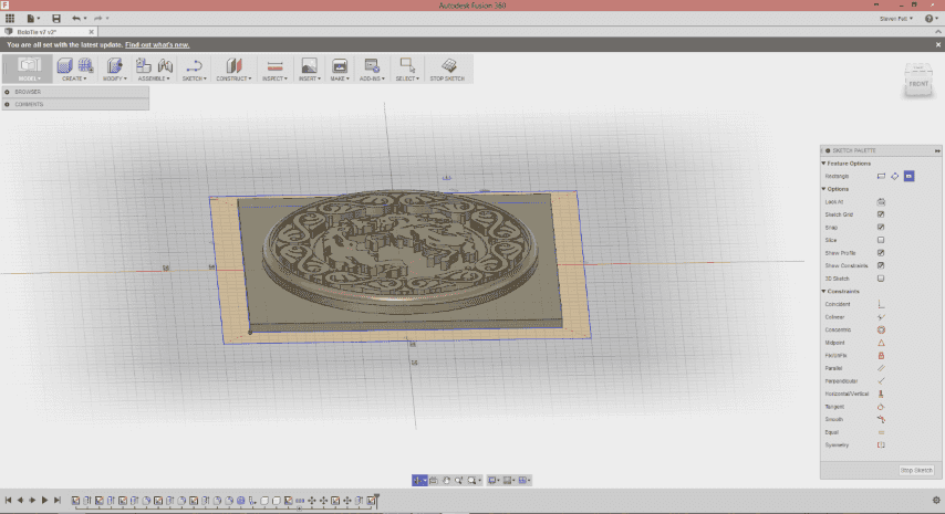
I started with an Image I made quite a while ago. I resized the center image inside the filigree ring and vectorized the image in Corel Draw and exported to a DXF. With this Vector File I imported my work into Fusion 360. Some of the geometry was not closed so I spent a bit of time chasing down and closing some of the open geometry.
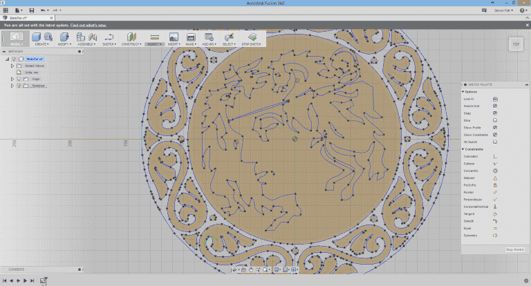
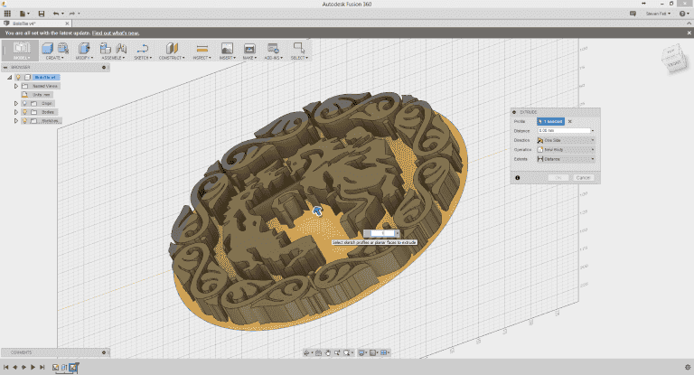
After repairing the image we are ready to define the boundaries of the broach.
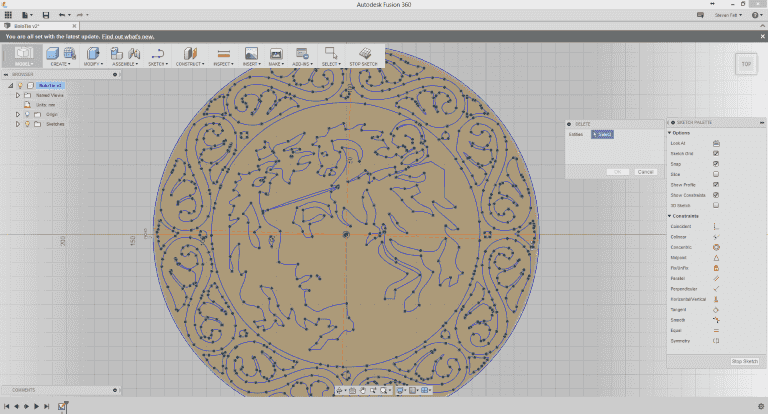
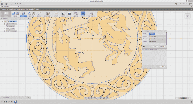
I then extruded my geometry 20mm.
I had to redraw my boundaries as Fusion 360 decided it wasn't important after leaving sketch mode.
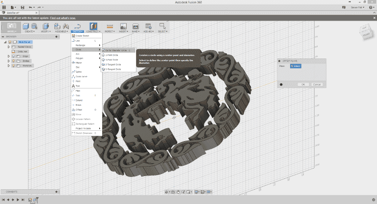
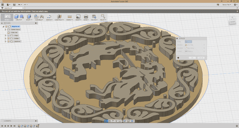
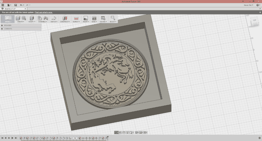
Extruding the base of the broach 10mm.
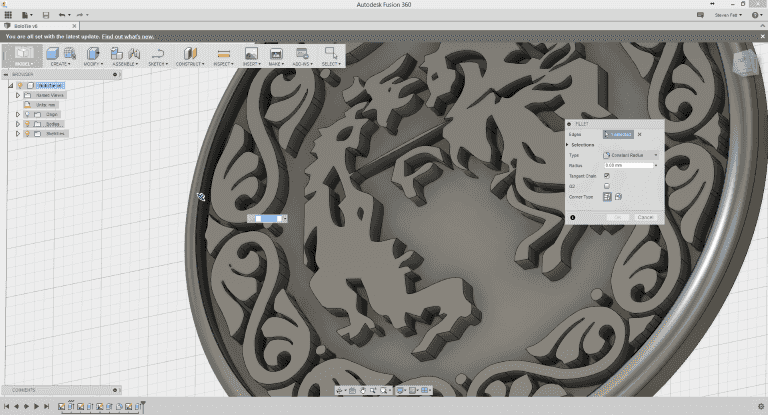
Drew a wider ring and extruded the LIP up 20mm, then gave the edge a small fillet.
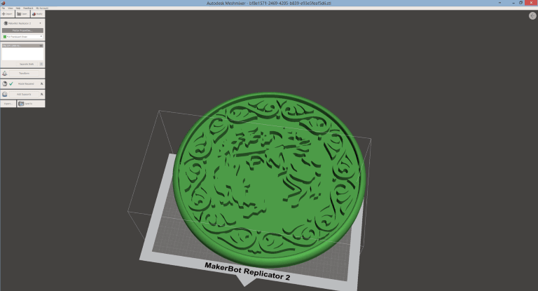
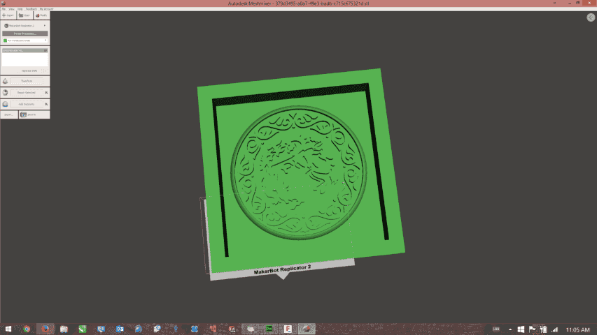
Export to MeshMixer, from MeshMixer to STL.
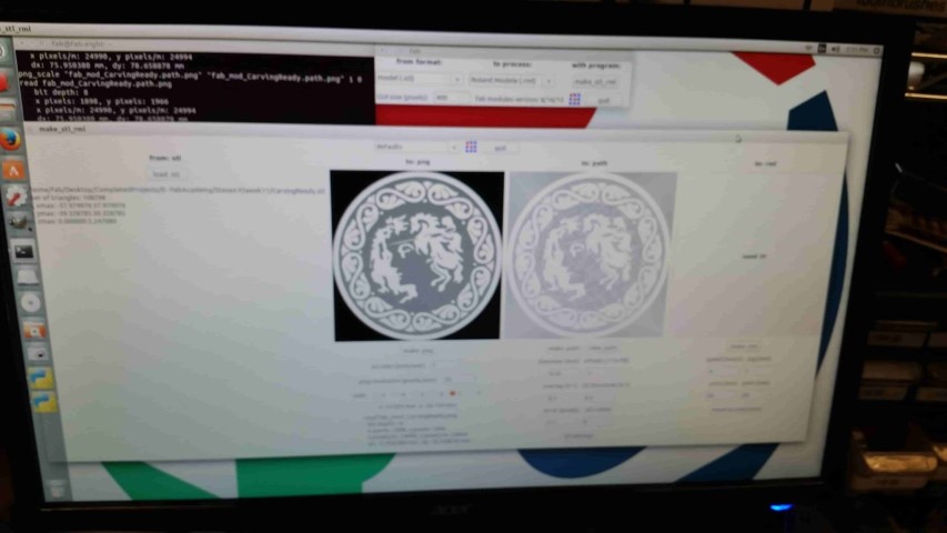
From within the Fab Module I ran STL To Modela(RML)
Imported my file. Clicked Make PNG. This creates a greyscale map of the depths of the object. I then selected 1/8thRough-MM and changed the bit diameter to .4mm. I increased the speed slightly since I didnt have to worry about foam breaking a bit.
Looks pretty dang good to me.
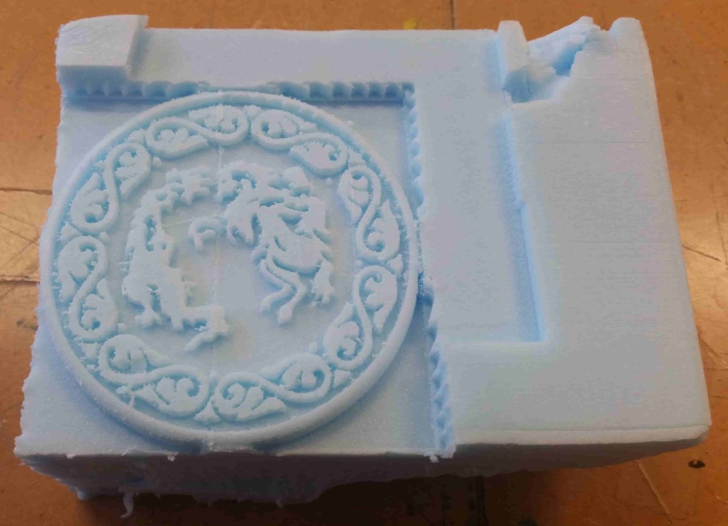
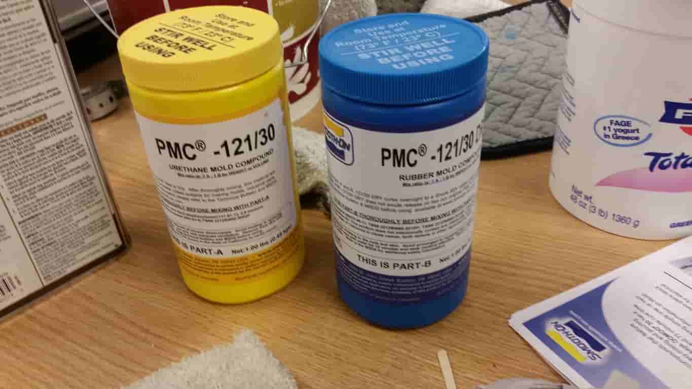
Let's make our mold now.
I ran the Job using the STL to RML feature of teh Fab module.
This Process takes a 3D STL file, converts it to a PNG using greyscale as a height map, then creates a tool path for the Modela from the HeightMap. I used the Default Settings for 1/8th inch rough.
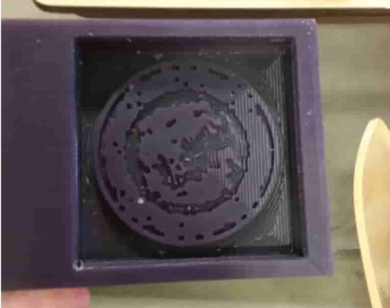
I mixed up a total of about 20 oz for the mold. More than I needed. Estimated 24 hour set time.
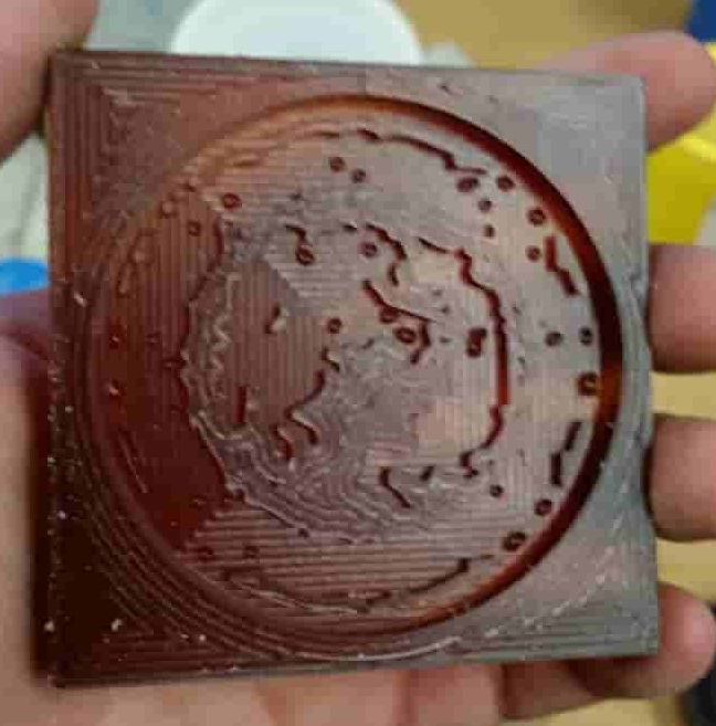
Not Too Shabby
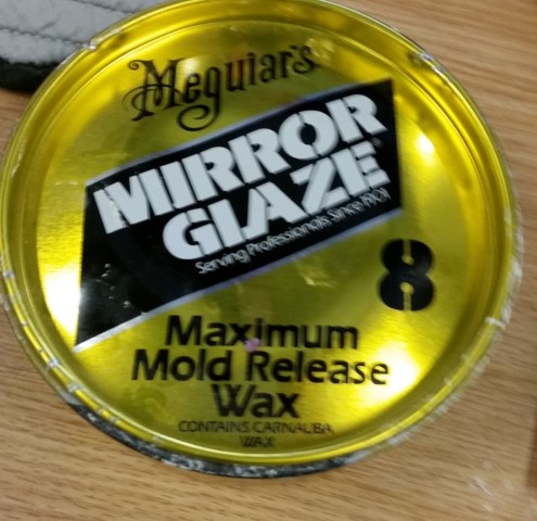
Apply a release agent
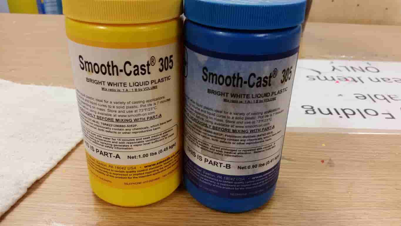
Equal Parts Smooth Cast. Sets in about 30 minutes
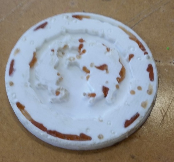
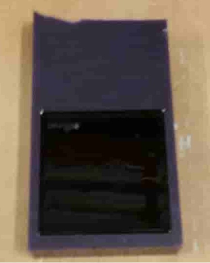
I didn't use enough Mold Release.
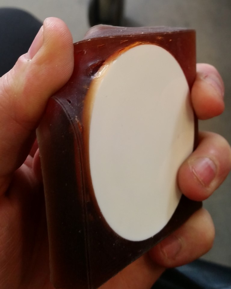
BONUS
This is what happens when you dont use ANY release agent