I began to debug my board and this was a big deal.
I connected the board to the AvrmkII programmer, The orange led was blinking that means something was wrong in the reset line.
I checked the soldering many times, everything was well connected and there was no short cuts...
Seeing my disapointment, our big Gégé (a student-277- of Fablab Ajaccio ) decided to save the day to me...
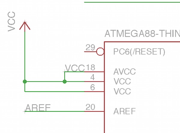
In less than a minute, he found the error on my board, the Vcc was missing on the reset line and the RST not connected...
Thank's Gé !
I opened Eagle and redraw the schematics.
RST is not connected in this case ....
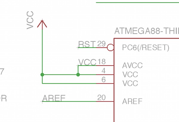
Here's the corrected schematics:
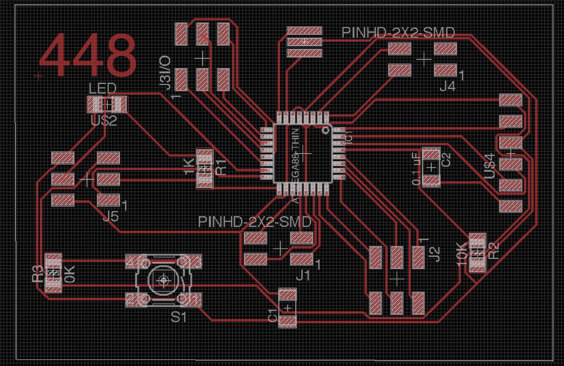
I changed some details like outline size and added border radius with Inkscape.Then soldering, again...
I plugged the AVRmkII and miracle: It works.
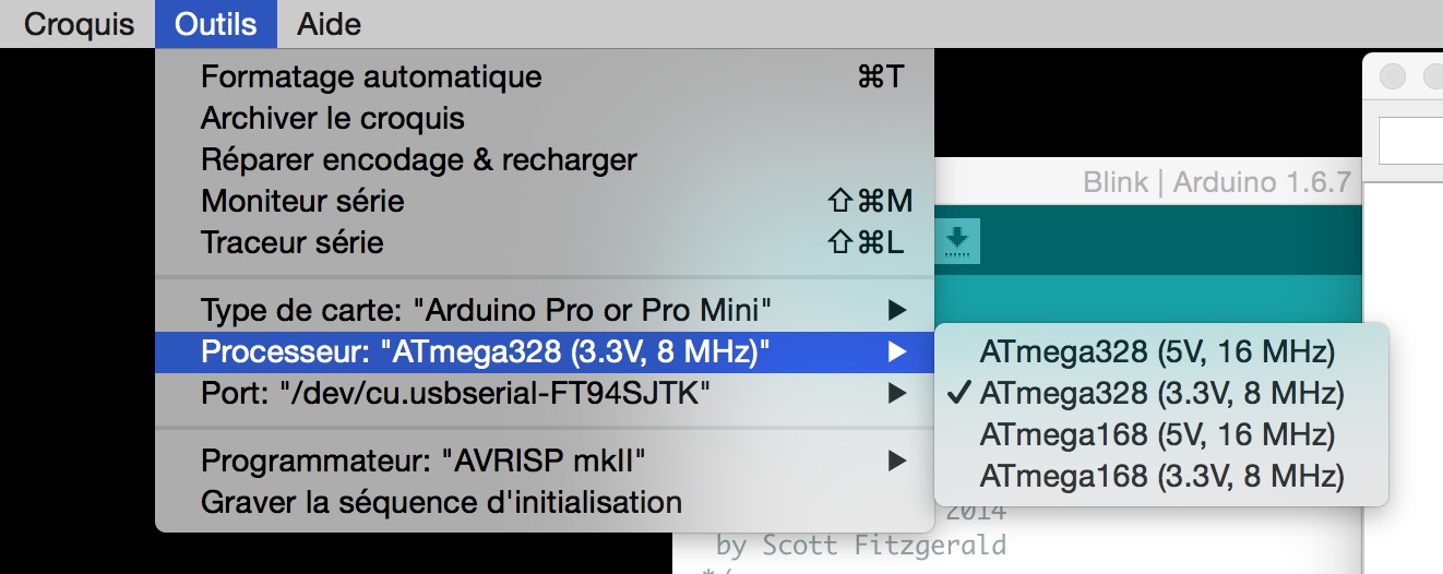
I burned the boot sequence with Arduino, I thought it was the easiest way to do it.
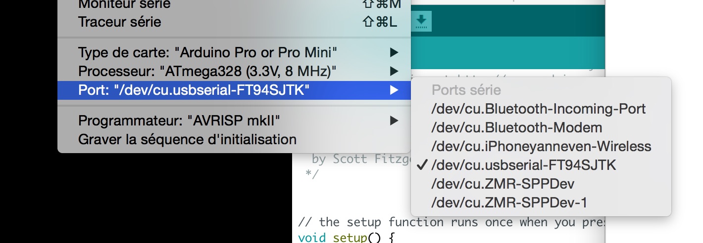
Here's the different steps to do it:
Choose the correct type of board: Arduino pro or mini in my case.
select the right port : dev/cu/usbserialFT94SJTK
Set the correct clock speed and current voltage: 8Mhz at 3,3V.
select the good type of programmer : AvrmkII.
click the burning process button and magically you have an Arduino !
I loaded the "blink" example : everything was ok.
I have never looked at blinking Led with so much pleasure !
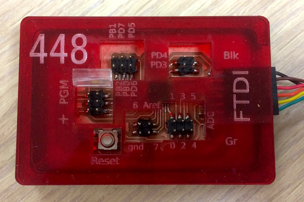
Finally, I decided to make a red acrylic box to protect my board.
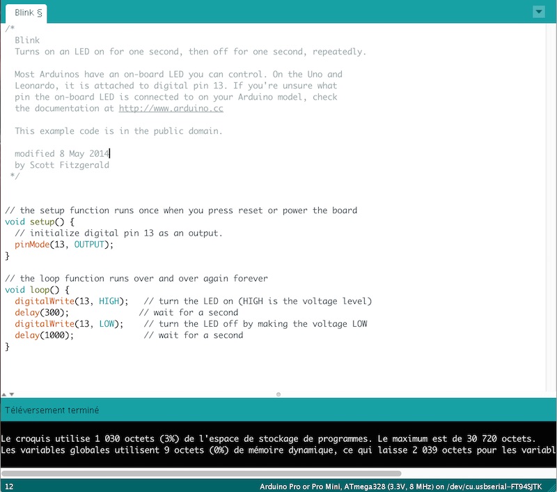
Let's begin to work with Arduino and start programming. First I try the classic blink.
The way I did it :
first thing, declare the pin 13 as an output in the void setup : pinMode(13, OUTPUT);
then, in the void loop, write an high level on pin 13 : digitalWrite(13, HIGH);
pause the program during 300 ms : delay(300);
write a low level on pin 13 : digitalWrite(13, LOW);
pause the program during 1s : delay(1000);
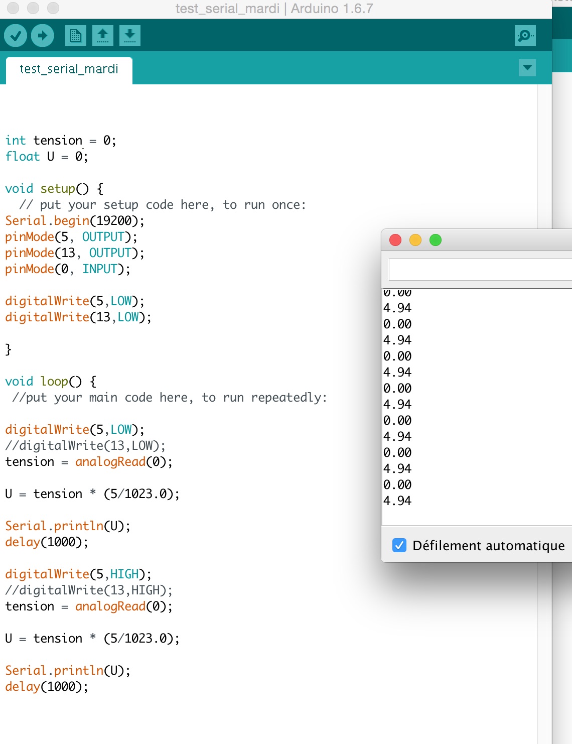
I also try to make a sketch using read.serial to see the voltage applied to the led:


