Design and build a wired &/or wireless network connecting at least two processors; this is our assignment this week.
I decided to make something useful to my final project:
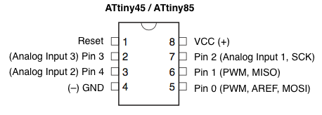
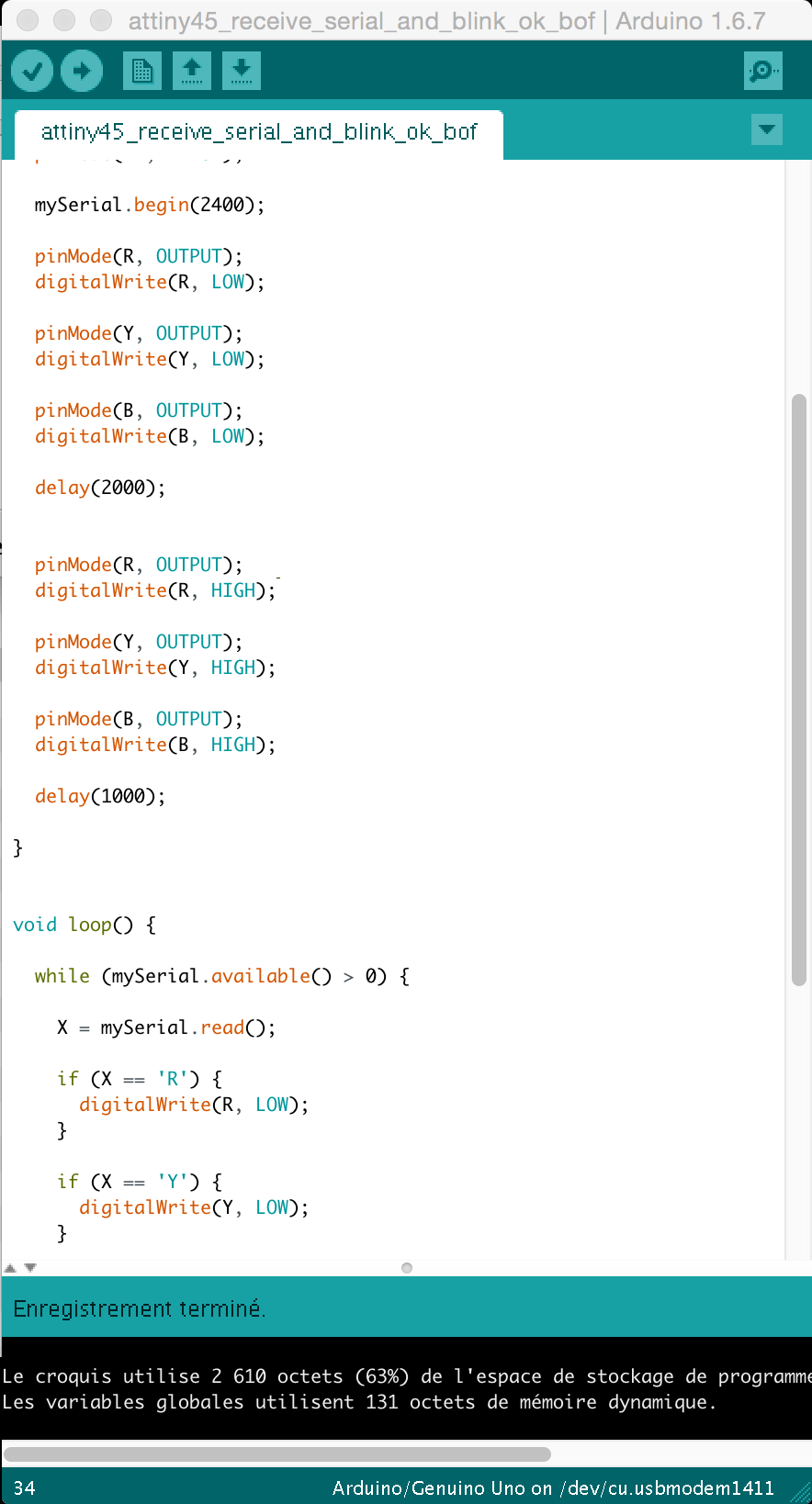
A little board with an ATtinny 45 wich could receive serial from my own hello arduino and manage the display panel.
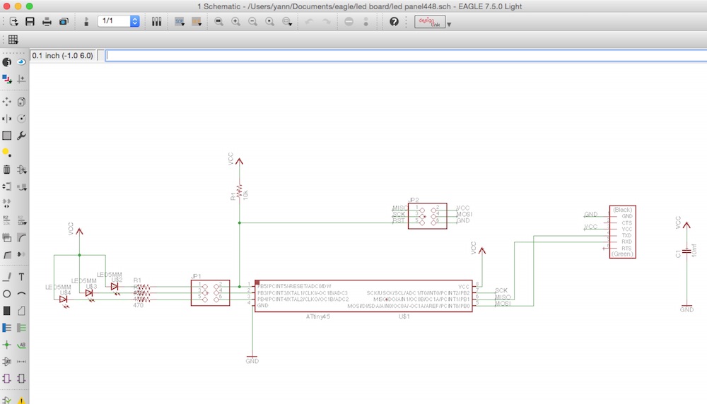
As usual, the first step is to design the board with Eagle.
Here's the schematic:
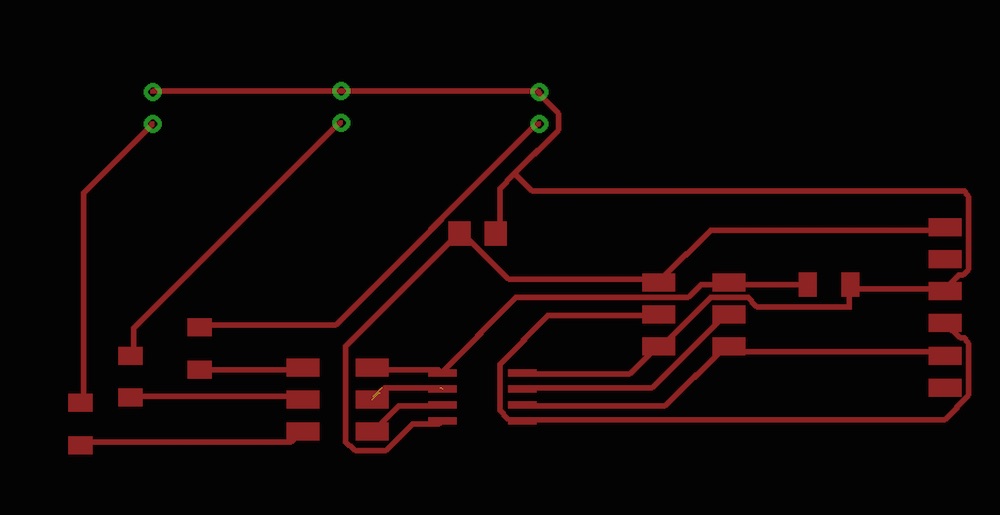
And this is the board:
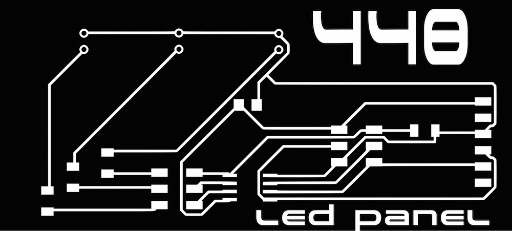
I added little corrections with Inkscape.
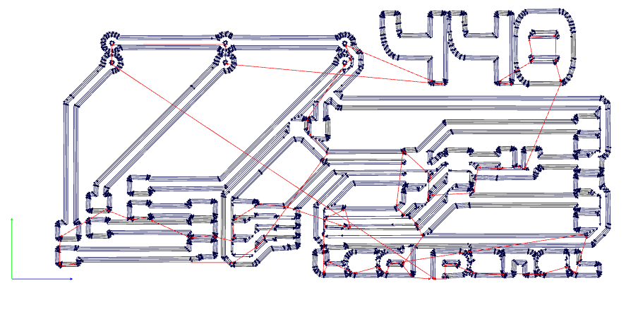
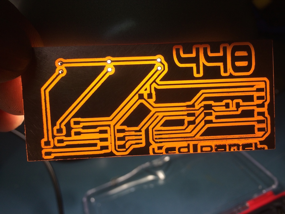
And sent the file to Fabmodules with the correct set up.
Here's the result:
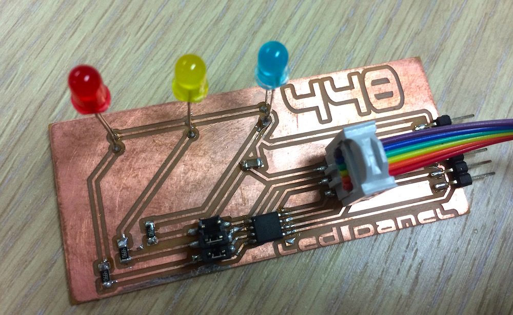
Then soldering.
As there isn't enough pins on the 45, I put jumpers on RST, PB3, PB4, and I realized later that using the RST pin was not a good idea...
I changed my mind and choose the PB2 to connect my blue led. I had to use a little strap for that.
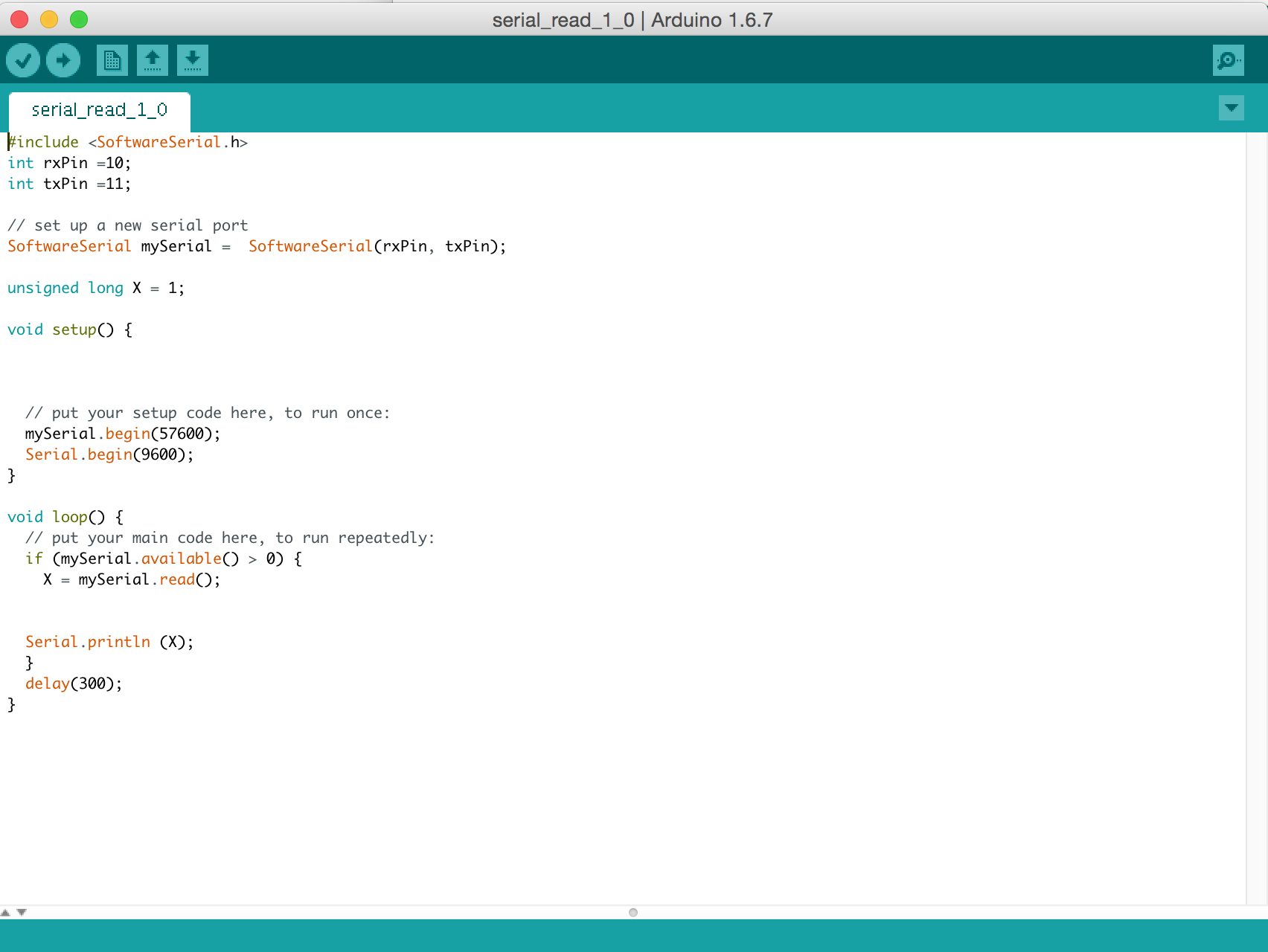
And programming.
Why this board ?
To give informations about supply, DMX presence, WIFI or Bluetooth link.
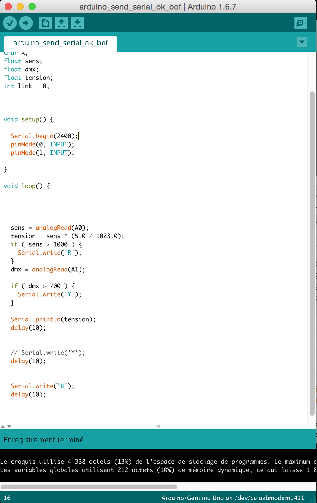
VCC connected to A0 analog input, if the tension is above 4.8V the red led is ON.
Serial TX connected to A1 analog input, if signal is present the Yellow led is ON.
If a WIFI or bluetooth link exists, the blue led is ON.
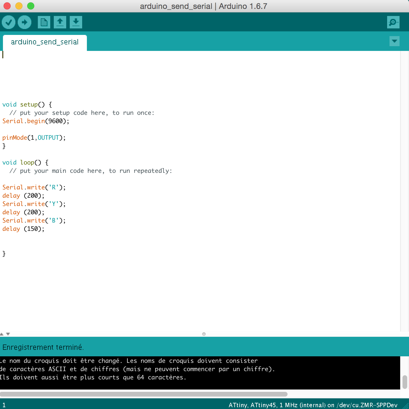
I want my arduino card to send status of three leds by serial to the Attiny .
It wasn't operating immediately....
A few days later:
Gimli helped me... again. ( Gimli is Gérard Bandini student/277 He helped me a lot during this Fabacademy...)
He gave me a few tricks. It's fixed now:
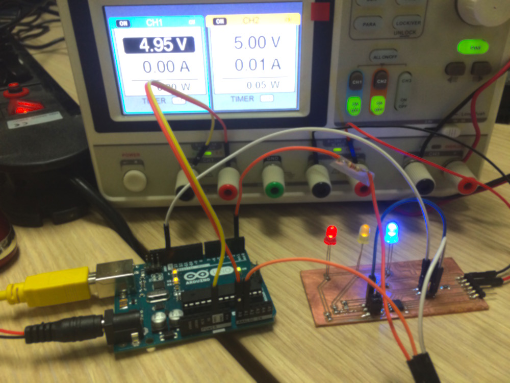
I didn't want to take risks: as my own Hello Arduino was installed in my final project, I used a commercial Arduino Uno to make some tests.
After that, I tried the board with my own board with the same results.
NB: The Blue led was a little bit more shinny than the others, in the final project, I had a 500 ohms resistor to this led, the three diodes have same level now.
