WEEK|09 / 10
Mechanical & Machine Design
For this week assignement, we have to make a machine that make. This is a group project.
Software used
Common software was used for this task :
- FreeCAD
- Inkscape
- Skype, for scheduled meetings
- The Gimp for image processing
- Bluefish
- Git
Source files
Did I do that elsewhere ?
Here is the assignements where I had to use these skills :
Our idea
We decided to make a drawing machine, with the design based on the AxiDraw
Unlike the AxiDraw, we wanted to use triangular section for the axis, giving a more rigid structure.
Unlike the AxiDraw, we used the lead screws present in the kit, no timing belt, this mean that we are limiting the axis amplitude.
Task repartition
Due to the schedule of all of us, we knew we cannot be regularly all together at the same time in the fablab.
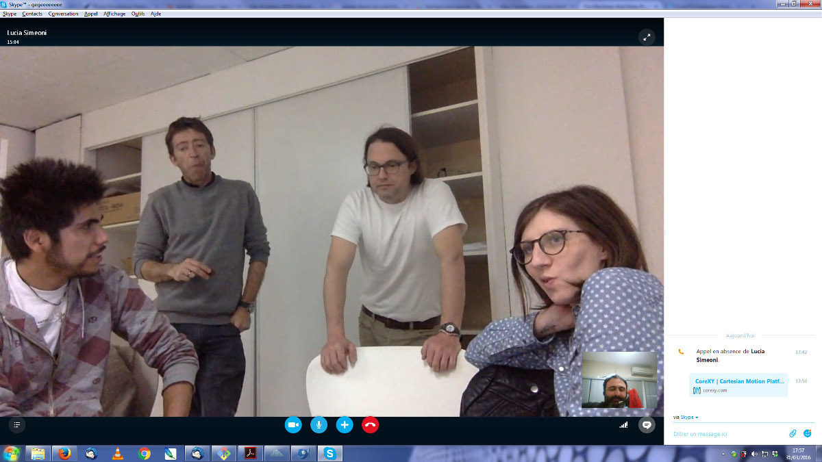
We've done several skype meeting during this weeks to organize ourselves.
So, our dream team shared some tasks for this project :
- Yann and me were focusing on tinkering and building structure
- I also made/hack the pen holder stuff
- Lucia will make this structure more beautiful and was in charge of the common documentation
- Frithjof is in charge of software development
Of course, having our roles assigned doesn't mean that we didn't be involved in the other students tasks !
Designing the machine
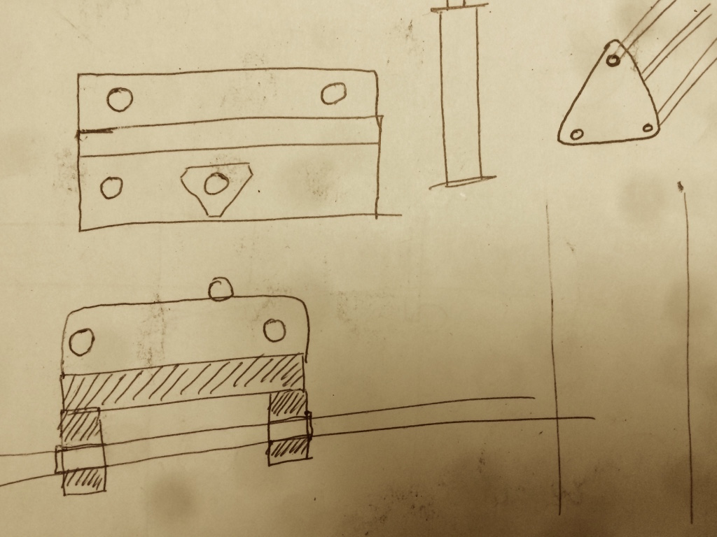
Yann and me begun to tinker about the global structure of the machine. We choosed to go with triangular section because it allows a more rigid structure and it dispatch the mechanical stress accros 3 points instead of 2.
First sketches, photo courtesy of Yann
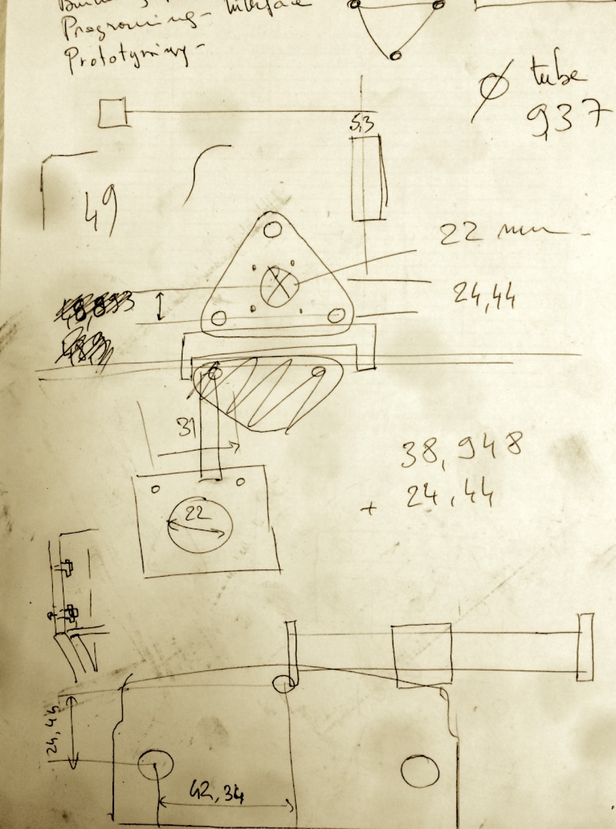
Unlike the original AxiDraw, we only have motors with leadscrews, no timing-belt. Due to this, we couldn't use the CoreXY mechanical structure, that's why we choosed the classic cartesian style.
 Arms are bigger on this design than real, we cutted the aluminium tubes lately to keep some safety margin while tinkering.
CAD parts
Structural parts
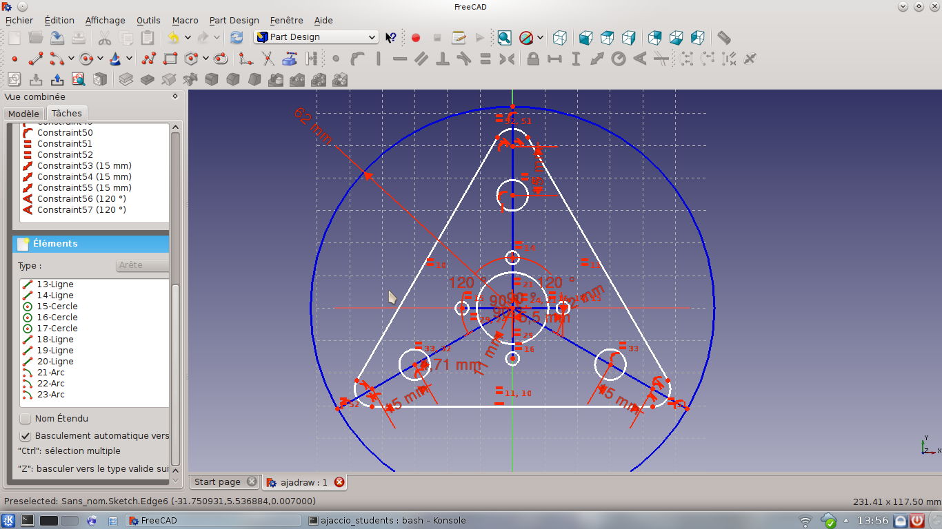
So, now that we have a design, we started to draw our parts. I drawn the triangular sections (actually three, with some variations for motor fixations or aesthetical reasons) and also the feet (but those wasn't the ones used in the final design).
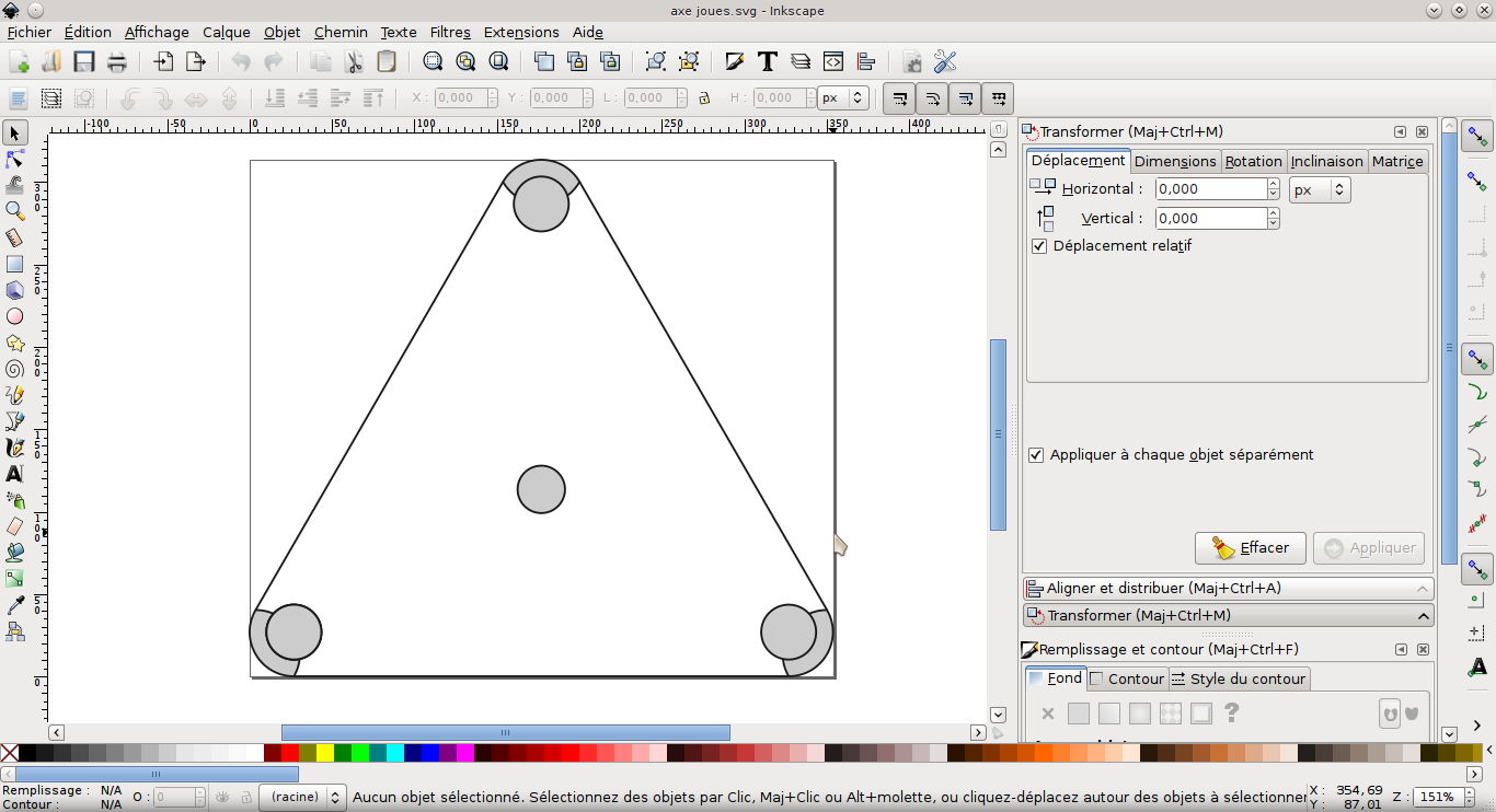
Exporting the designed parts in SVG is really not convenient in FreeCAD, there are 3 "SVG" exports :
- 3D view
- Flatened SVG
- Drawing
Lines are in fact rectangular shapes, not linked together, rounded borders two intersecting circles... all this crap needs to be cleaned before any cutting, or it will ruin the material when lasercutted. To clean the outline, I deleted all useless segments on the rounded borders, combined all lines of the outline (CTRL+K) and used the "simplify" command from inkscape's "path" menu, the shape is thin enough so this tool will simple delete one of two near points.
After this process is done, the remaining steps are nothing fancy (clear the filling, set the right border thickness/color, etc...)
Still enough, this cleanup wasn't perfect, more on that later
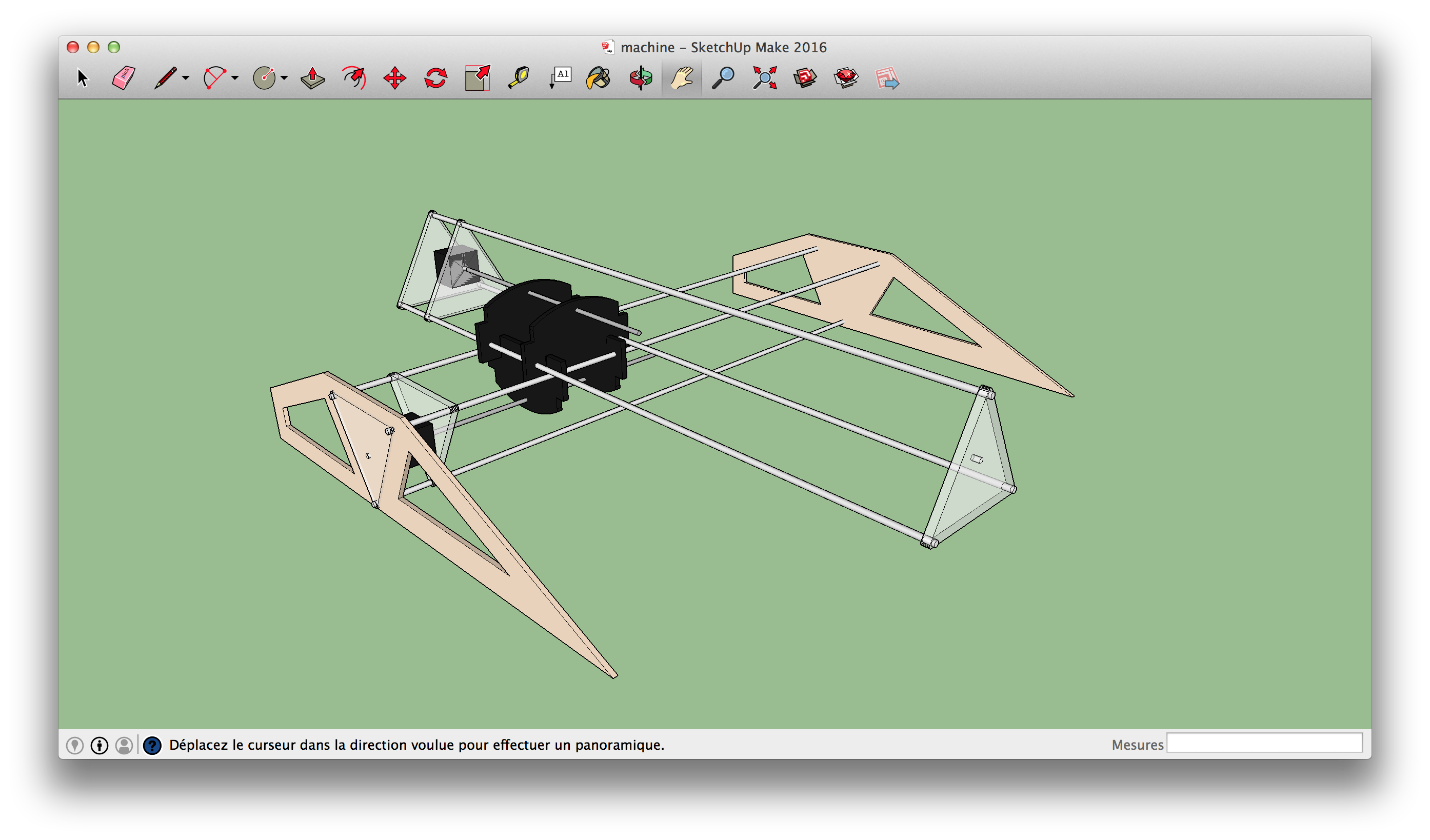
Once assembled, the axis looks great (aluminium tubes still needs to be cutted)
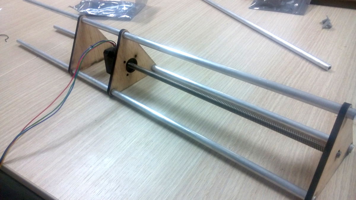
The triangles has been slightly redesigned later, adding two slots to allow the XY-Carriage travel and gain some centimeters.
XY Dual-Carriage
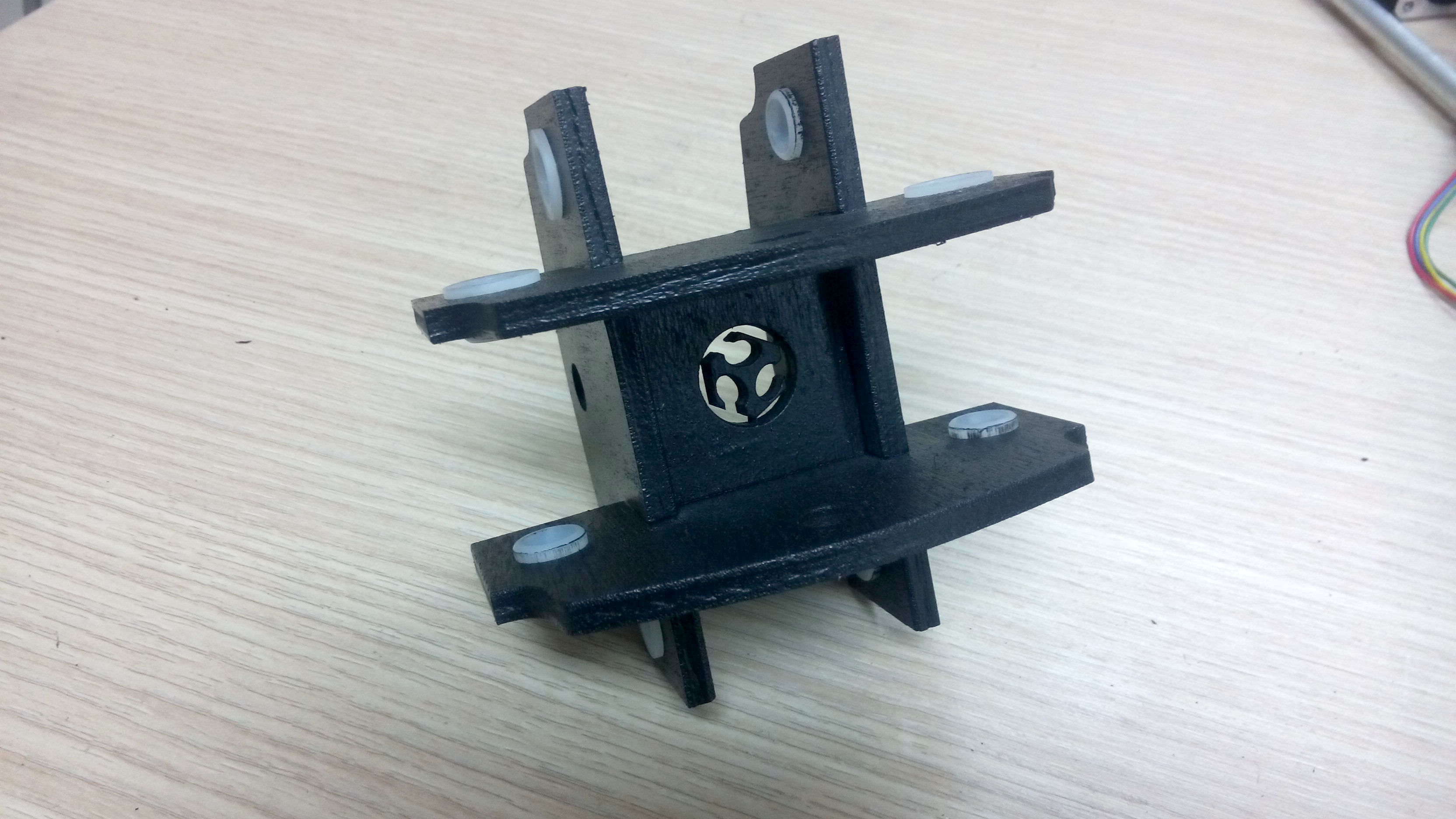
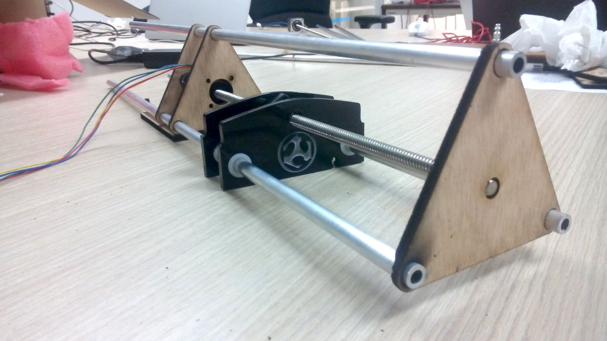
The dual carriage is in fact two simple carriage fixed together. As we can see in the pictures. This gives our machine a modular style, so the axis could take several shapes, not only a cross one
Once assembled, the two axis looks like this :
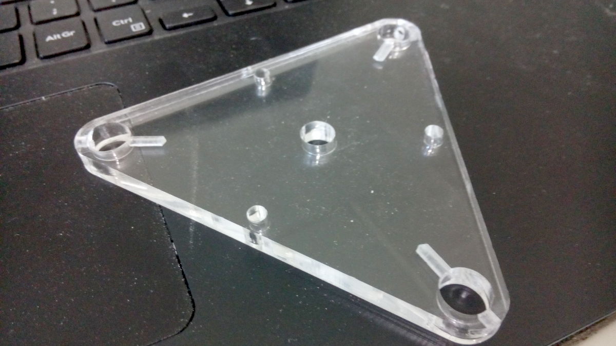
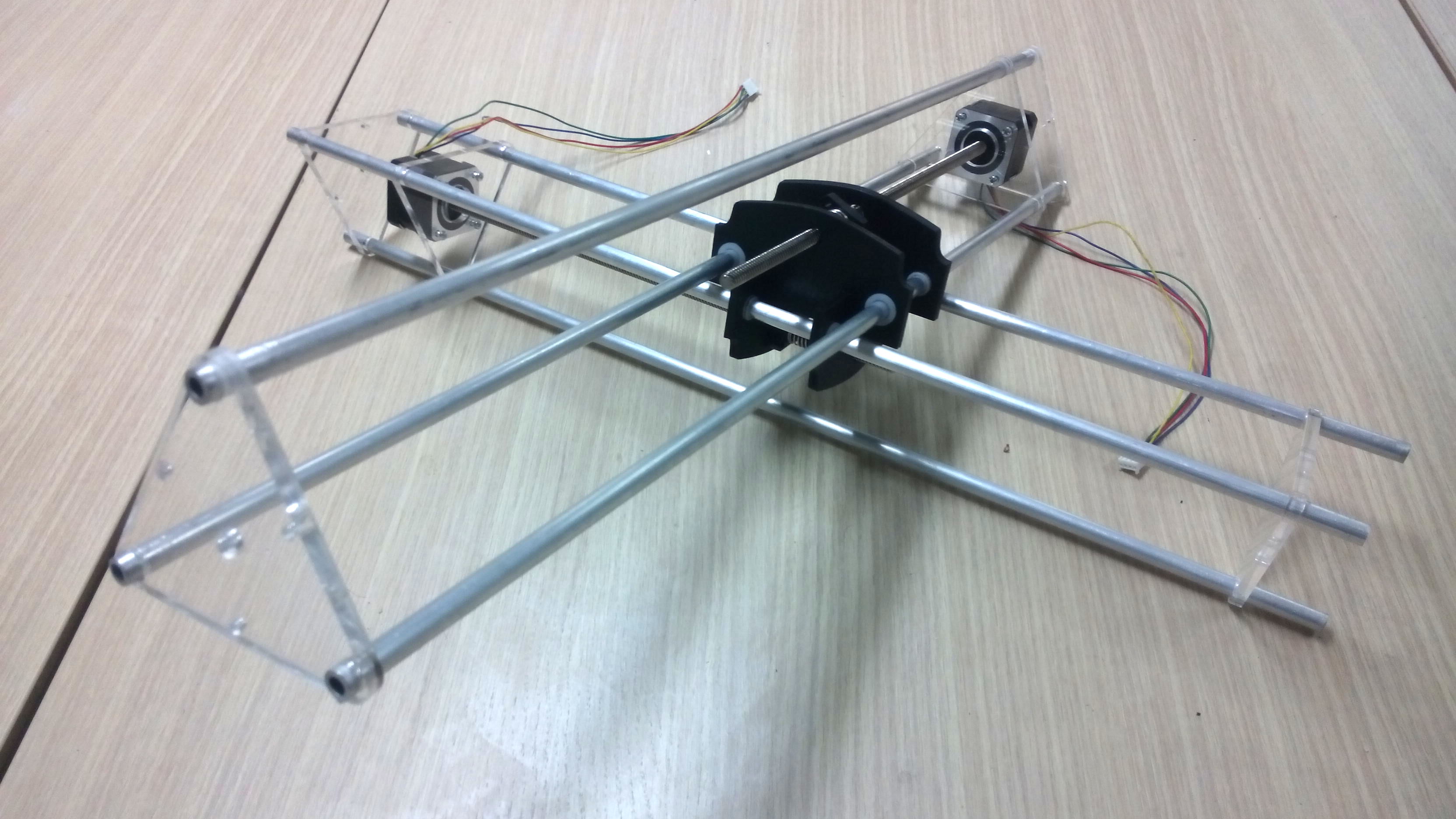 Note : the triangular section have finally been cutted in clear acrylic, because, you know, look & feel.
At this stage, our machine can be operated by hand, the axis moves fine, but because all the structural part aren't fixed yet, it's not really convenient.
Pen holder parts
When tinkering about how the pen holder should work, we focused on using servo to lift up and down the pen. The problem is that we didn't really know if the Gestalt boards could manage the servo.
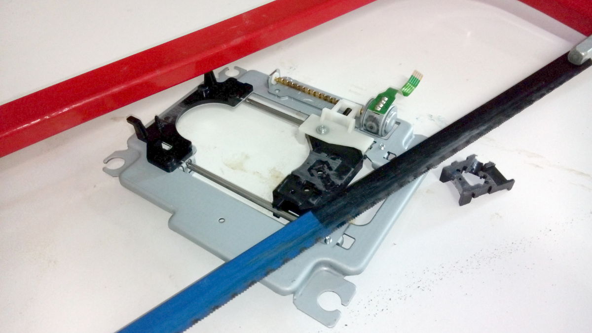
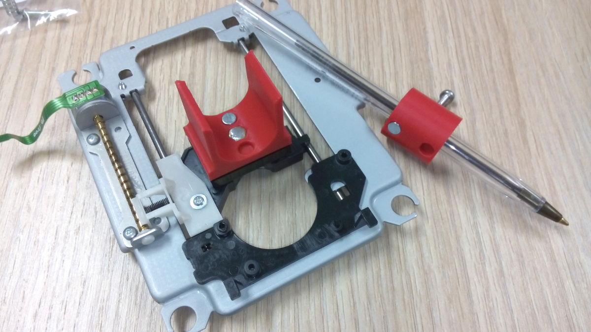
After some tens of minutes of tinkering, a good solution popped on our mind : why not salvage an old CD-Rom Reader and use this tiny but precise mechanics? It has stepper, it is already assembled... and the distance between his fixation holes is exactly the same than between our aluminium tube (who talk about luck here ?!).
All we had to do is to adapt the pen holder on it ! Let's go !
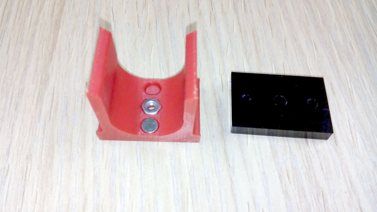
 The pen holder will be made of four parts :
- The CD-Rom carriage, already here, just need to be adapted
- The support
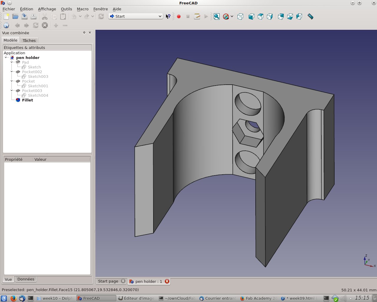
- The pen holder
- Some quasi-tubes in witch the pens will be inserted
the pen holder is C-shaped, the tube containing the pen will go inside. He also has two holes on the inner side, where two small neodymium magnets would be glued. There would be two matching magnet on the tubes. This will allow for a quick-change of the pen while drawing.
This gives also a safety margin in case of a pen crash - the tube will simply go off the holder.
Tubes are like consommable, we could print as much as we need, using various hole diameters for different kind of pen.
Before begining a "drawing" session, one would simply prepare every pen colors (taking care of the "Z", i.e. using a jig) and quickly switch between them for each color.
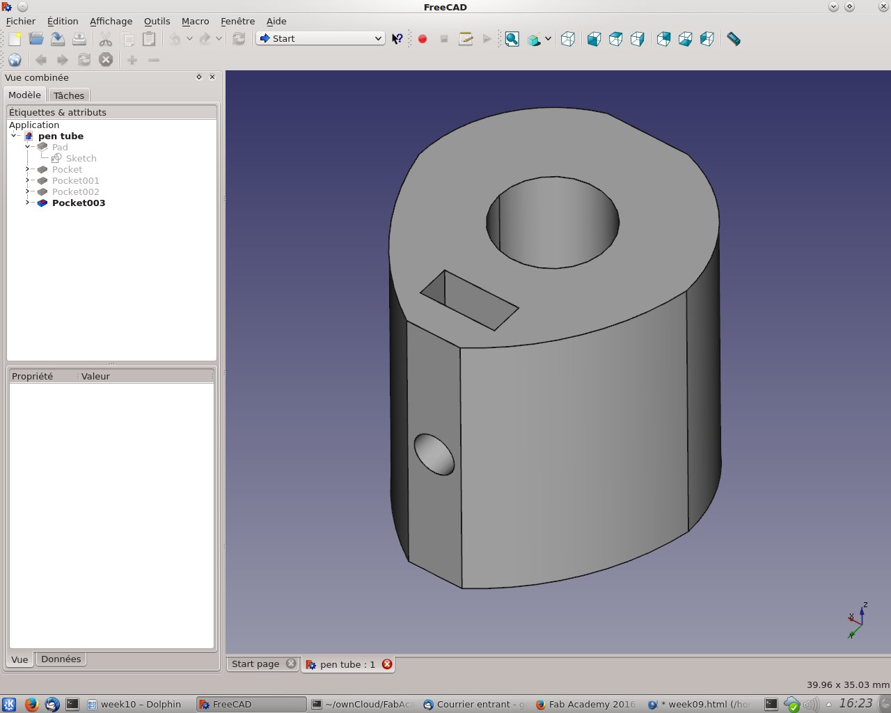 The tube has been slightly redesigned since the photo was taken, to allow inserting a nut inside a hole, to fix the pen without more strongly and reliably.
Tubes and fixation
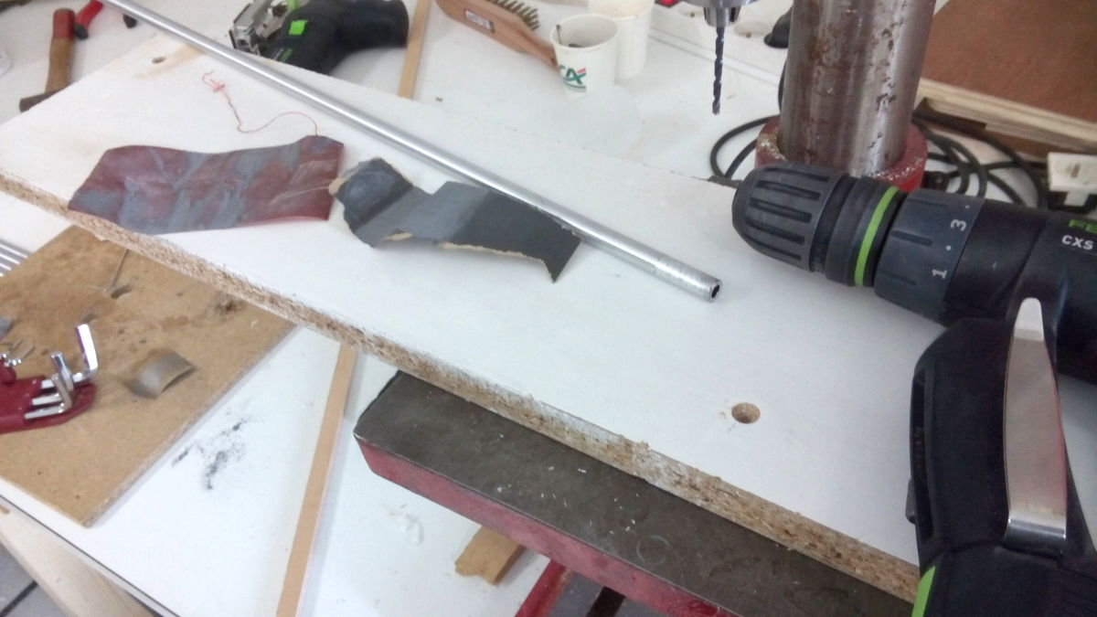
The aluminium tubes present in the kit are way longer for this machine, so we need to cut them.
For the fixation of all the structure, firstly, we wanted to use epoxy to glue the tubes to the triangles, but this would be an error, because further tear down would be impossible. So we drilled some holes in all the angles and the tubes to fix them with screws.
I also sanded all the tubes, to have a smooth finish, this would also be better for the nylon bushings, and looks way better too
Gestalt and CD-Rom Reader
Frithjof is in charge of the programming task, and I tried to help him while he was tinkering about how to make gestalt moving the little stepper
Mistakes and troubles
Messy export
When exporting SVG with FreeCAD, the resulting file is messy as explained above. Cleaning the file as mentioned worked, but it's still not perfect.
The reason is that all the lines of the outline, even when combined, are still standalone lines. Boolean "Union" or "Join nodes with segment" didn't change anything. This resulted in the lasercutter doing two passes on the outline, in a weird order.
Even if the resulting pieces wasn't bad, it's annoying !
After some time passed on inkscape to try to understand, I found a way to cleanly workaround this problem :
For an unknown reason, straight lines can't be linked to rounded borders, but corners extremity can ! So I just had to delete the straight lines, and joins the corner's extremities together and voilà ! A good shape, fully closed.
Damned that I found that after all the lasercuts was done.
Tubes diameter variation
Nothing really bad here, but ONE of the six tubes was 9,7mm diameter instead of 9,4mm. Of course, this difference popped up when trying to insert this tube on a triangle, because we didn't measure all the tubes at first.
For the first prototypes, we only sanded the hole to make it bigger, but later I updated the design to enlarge the holes size
CD-reader stepper weird behaviour
While I was tinkering with Frithjof about the CD-reader stepper, our first tests demonstrated some weird behaviour. The stepper was running good, then bad, then not at all, then almost good, then almost bad... At the end of the day, we didn't solve the problem. My guesses are :
- Bad current settings ? Too much or not enough current ?
- Microstepping issue ? The motor didn't run smoothly, may be this little motor does not react in a good way with microstepping ?
- Rotation/Pulses speed too high ? Informations found on Internet states that this motors have a few steps (about 20 for a single rotation), maybe a high speed will make the motor miss some steps ?