3D scanning and printing
Additive Manufacturing
This Week's Assignment:
The assignment for this week is to learn about 3D printing and scanning. See detail here.
-
Test the design rules for your printer
Print and Test anything
-
3D Print Your Own Designed Ojbect
(Small, few cm) that could not be made subtractively
-
3D Scan Any Object
Optionally print it, note : (extra credit: make your own scanner)
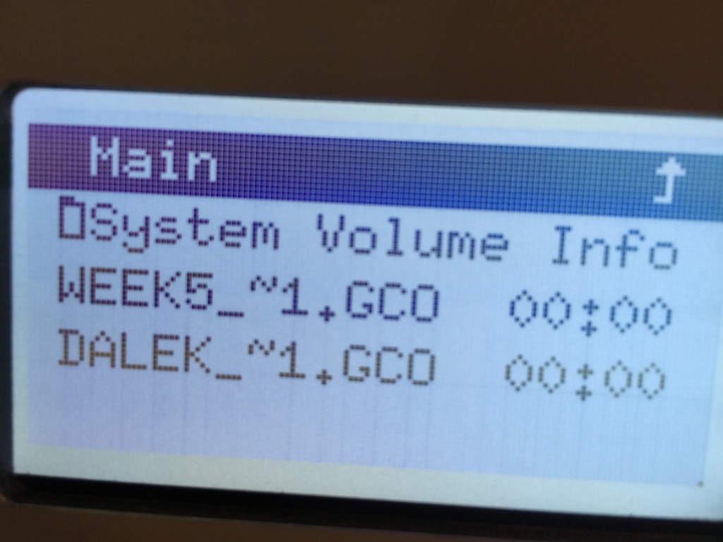
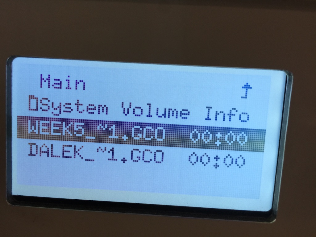
Files
All files can be download here.
Testing the Machine Design rules
Print anything
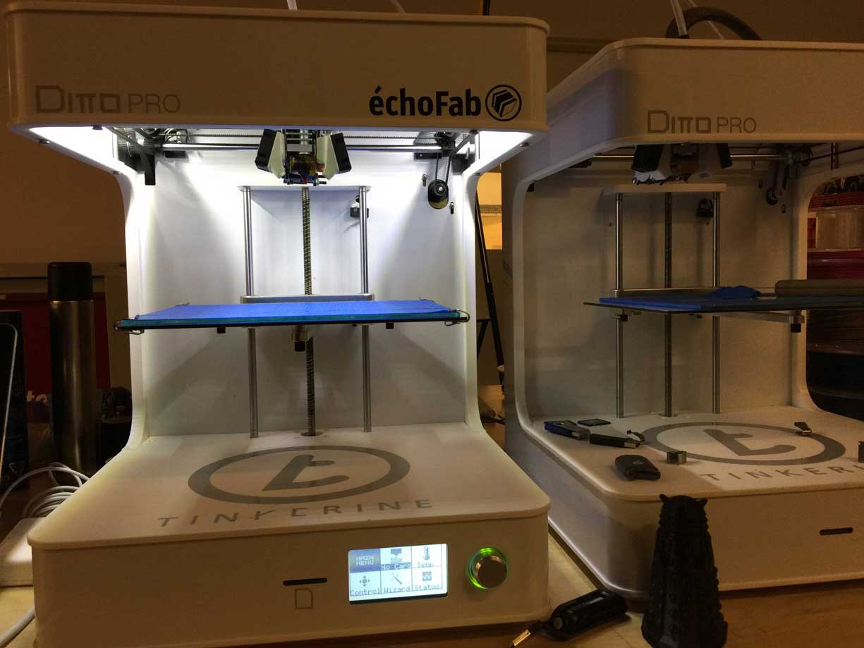
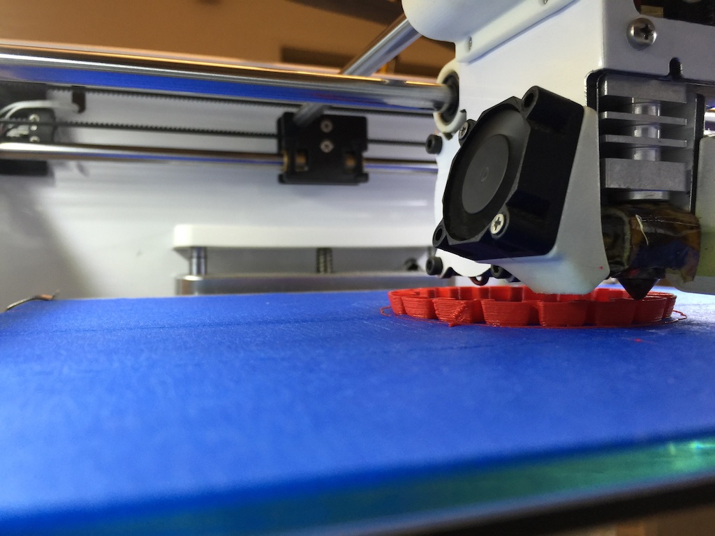
We have two printers at échoFab Fab Lab in Montreal, Quebec, Canadab. The the Ditto, which can only print in PLA. It is well made and easy to use. The size we can print is aproximatively 7"X9"X9. We use Cura, an open source software to print. It is simple and simple to use. There is also anothera G-code generator for 3D printers often used called Slic3r.
Printer preferences
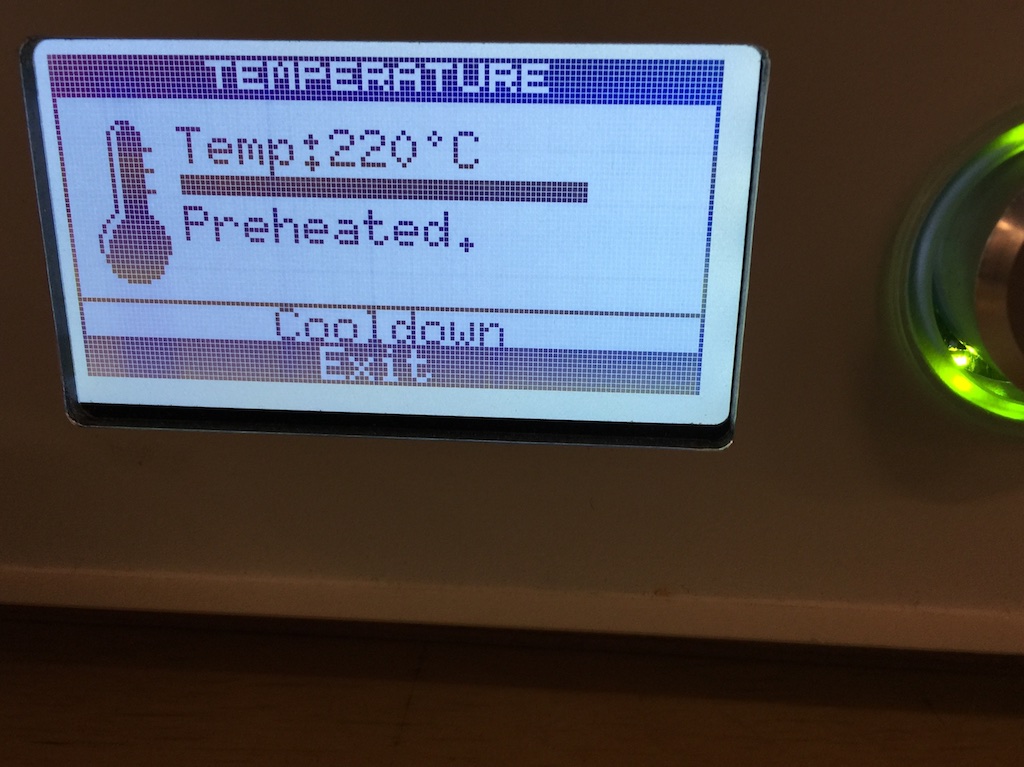
First thing I did was verifying printer preferences in the preference panel
- Dimensions & Weight
- External dimensions: 37 x 39 x 43.6 cm (14.6 x 15.4 x 17.2 in)
- Weight: 10 kg (22.0 lb)
- Printing
- Technology: Fused Filament Fabrication (FFF)
- Build dimensions: 22 x 16.5 x 22 cm (8.7 x 6.5 x 8.7 in)
- Build volume: 7986 cm3 (487 in3)
- Layer height: 50-300 microns (0.05-0.3 mm)
- Filament diameter: 1.75mm
- Nozzle diameter: 0.35mm
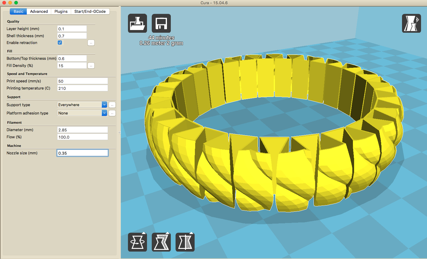
Part print settings
Below is the preferences I used to print:
Layer height is set to 0.1. I know that it is one of the most important thing that will determine the quality of my printed object because it sets the hight of the plastic that the header will put on each layer. So the smaller the height (mm), the finer the result. Normal print are 0.1mm and higher quality is 0.06. I can go up to 0.25mm for a very fast print at low quality.
Shell Thickness (mm) is the thickness of the of the outside shell in the horizontal direction. It is set to 0.7mm. I don not want it to be to thick otherwise the bracelet will lose it's fleibility.
Bottom and top thickness (mm) is set to 0.6mm. This part is pretty much self-explanied. I can be usefull for example when there is no support type enabled, it can sometime help the piece stay on the plate and not move if there are little surface on the bottom for exemple.
Support Type and Platforme adhesion Type are use to help print by creating a suport betwwen the piece and the build plate. Touching buildplate is the most commonly used. I set these to none as I dont need them. The bracelet has enough surface touching the platforme. Sometime we need to buil a raft which is a structure that is made to support pieces that has extrusion that will not sit on the plate. Has the printer can not print in the air. Like an elephant trunk.
The Dianmeter of the Filament is an important setting for having a good flow of plastic filament, which can also be set, of plastic comming out. Othervise some part may have too much or not enought plastics.
Learnings
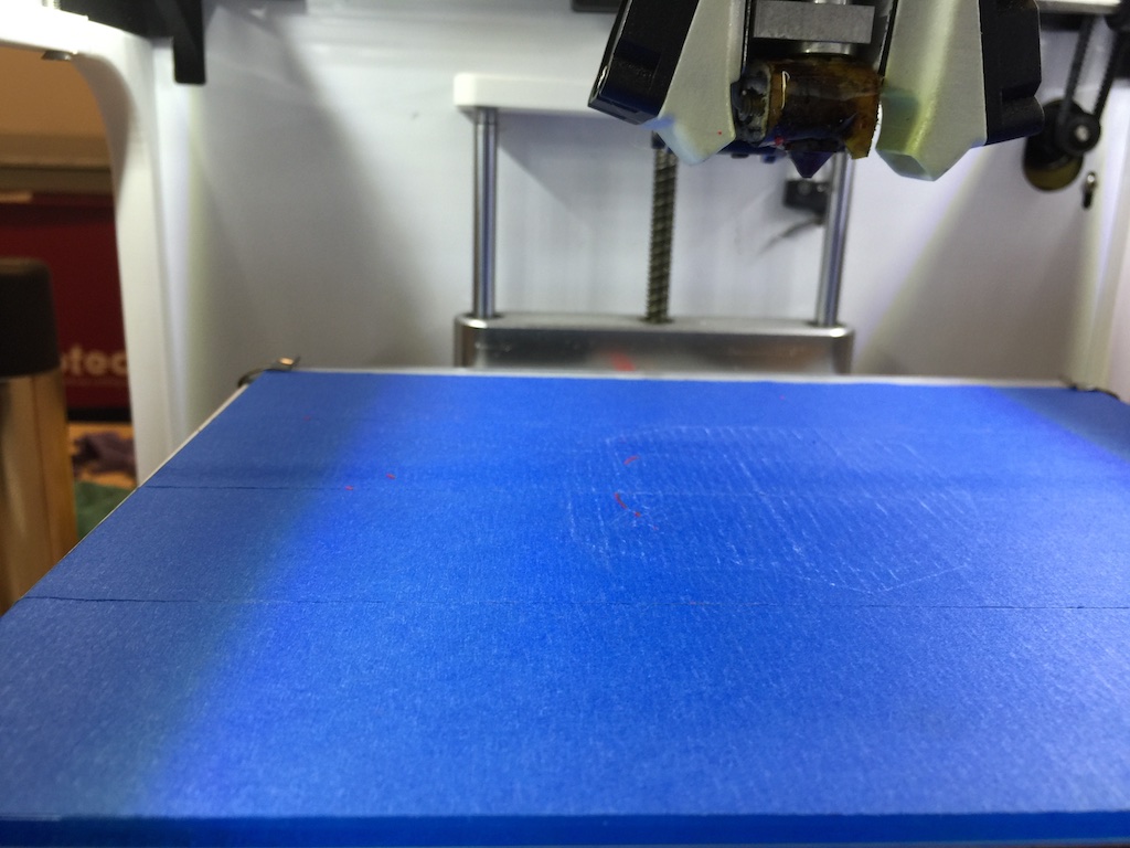
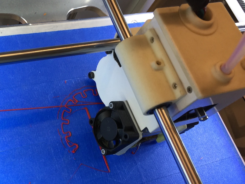
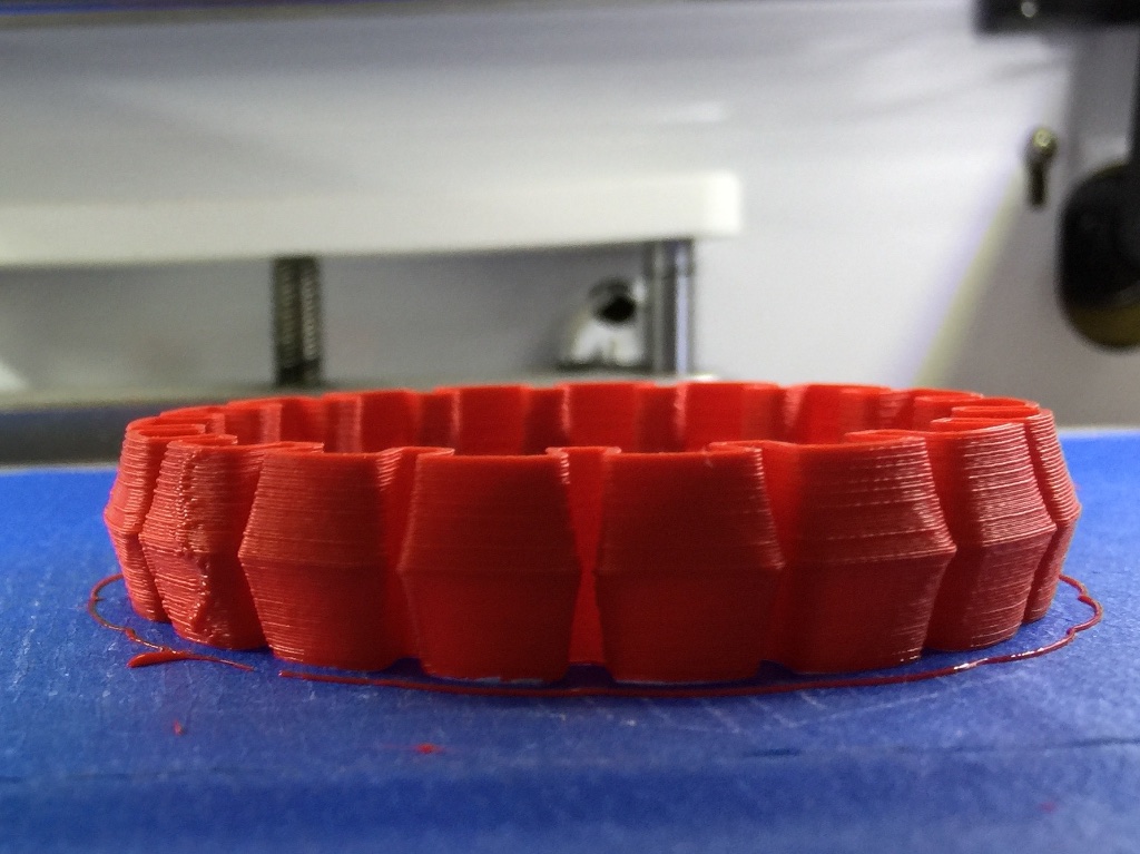
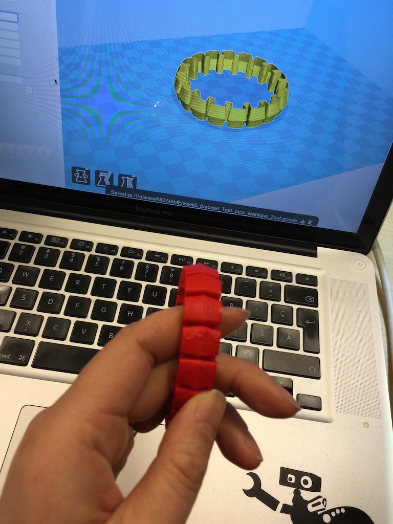
3D modeling may be obtain by different way: downloading, scanning or modeling in a 3D software. I use a file from Thingiverse web site to print a simple customizable bracelet. It is made by Emmett Lalish, an aerospace engineer that does 3D design for his hobies. This bracelet is very popular and I have since it in many makerFaire event printed. The band has a circular cross section, flattened on the sides to facilitate easy printing. You control the inner (wrist) diameter, the band diameter, and the number of notches. Files downloaded may be in different format, in the lab, we suggest downloading .STL, .OBJ, .DAE. I downloaded the .STL format and opened it in CURA software. The interface allows me to see the object in different angles (left click). For more information see the Cura tutorials. I taped the bed with masking tape and add a spray (3m spray or hair spray will do). We can also use water soluble glue stick such as Elmer's or Pritt washable glue sticks. I preheated the bed and printed the files. See the picture bellow.
Converting files
Meshlab is a free software tool that can convert several 3D CAD file formats.
import:PLY, STL, OFF, OBJ, 3DS, COLLADA, PTX, V3D, PTS, APTS, XYZ, GTS, TRI, ASC, X3D, X3DV, VRML, ALN
export:PLY, STL, OFF, OBJ, 3DS, COLLADA, VRML, DXF, GTS, U3D, IDTF, X3D
There is also an online converter online converter.
Readings for printers
- 3D printer review
- 3D Hubs made a 3D printer guide with 5 350 Reviews
- 13 Tools to Help You Become a 3D Printing Pro
3D print own design
My teacher Saverio told me that Rhino would be a nice application to learn. He uses it and it is easy to learn. I have used Solidworks before when designing my cube for my initial final project idea. At the time I did this spool design version 2 and have not yet made a third spool with Solidworks, like explained in week 02, Computer-aided design. So this is a version 2 of my spool design:
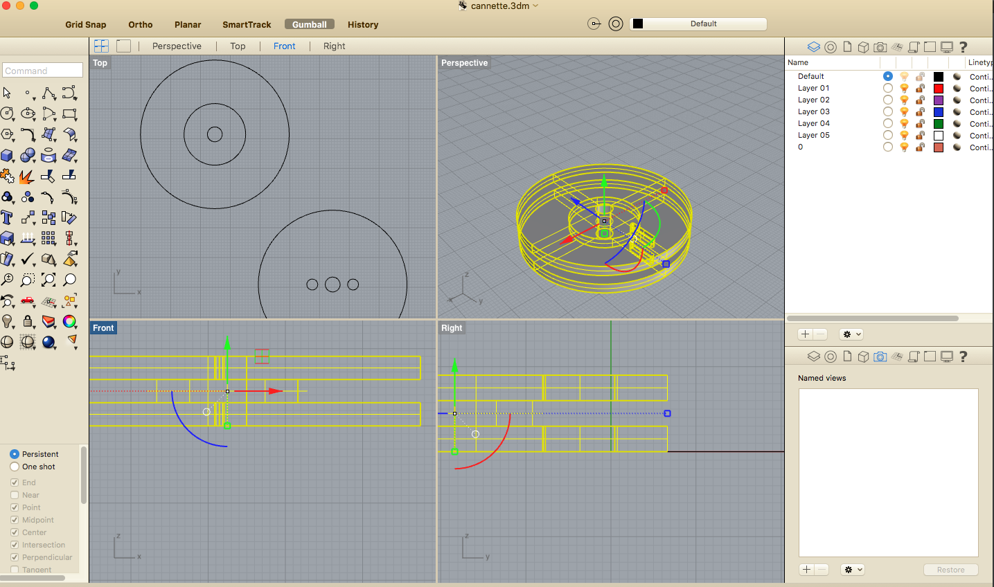
Creating a spool in Rhino is really intuitive in comparison to Solidworks where the learning curve is a lot bigger. I have used Photoshop and Illustrator before and it maybe viewed like that, palette tools are on the left and layers are on the right. There is vector drawing and then the possibility of extruding the object to make it in 3 dimensions. On the top left corner, a command line for typing the exact command in Rhino will help by filling it automatically instead of searching them in the main drop down menu which saves a lot of time. My friend Clement Langelin who showed me how to use it and objects litterally comes to life in a fraction of time, it can be amazing to watch him work. I wish I could have filmed him while I was in Woma Fab Lab in Paris.
I have not got the time to explore the analyse section and the rendering section, but will eventally. I still am undecided between adopting Solidworks or Rhino which is much less expensive and is compatible with my Mac.
Note: I am documenting this work at the end of my program studies and have made and use 3D application much more than week 05. Today I can speak with ease, but back then it was all pretty hard :)
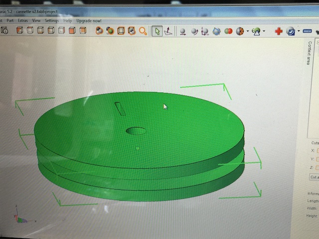
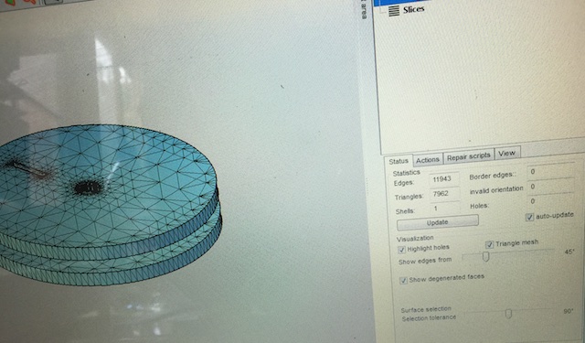
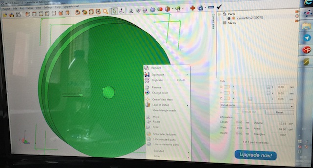
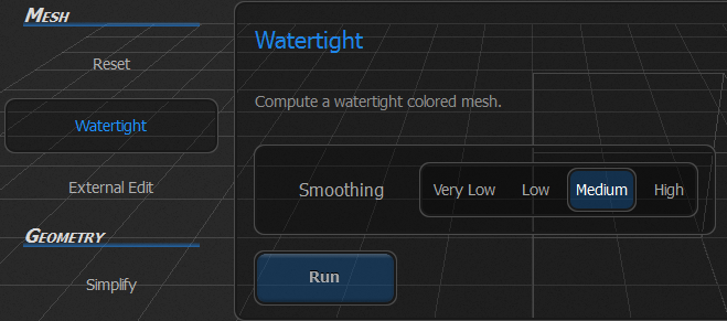
I then export my object in STL format and used Netfab Software to make sure the piece are joined and "Watertight", no left wholes.
This view is to see the mesh
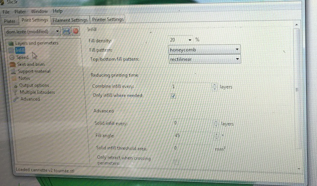
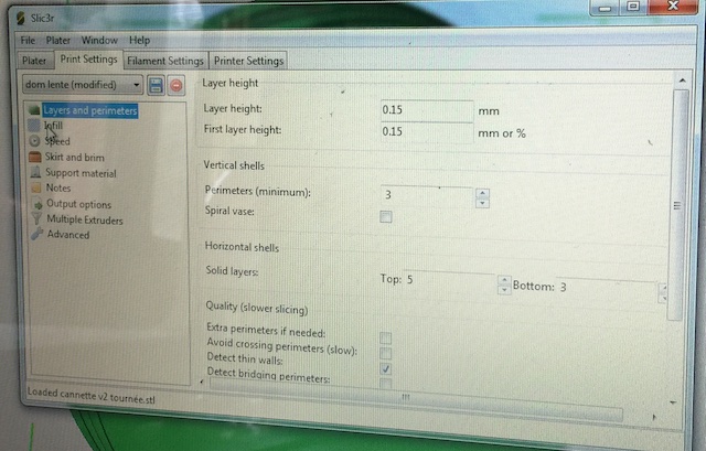
The file is then opened with slic3
Here are the preference of Slic3:
More preference settings:
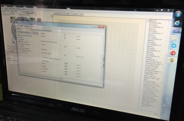
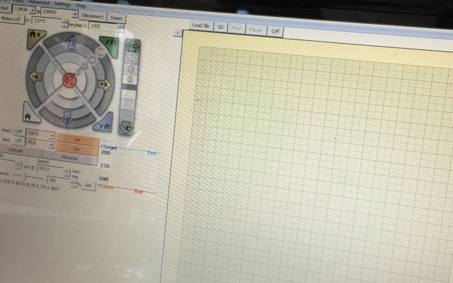
Than Pronterface is used for printing. This is a new way for me for printing 3D shapes. Big thanks to Julien, Maker of the Doode Printer from Doode Printer Studio for his help!!
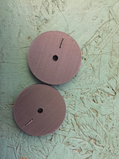
Result
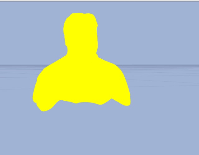
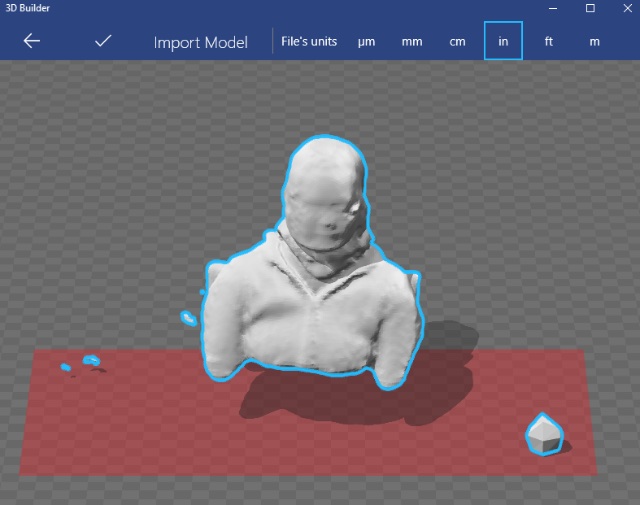
3D scan an object
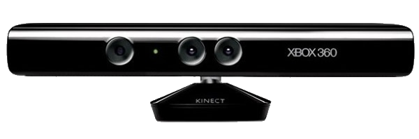
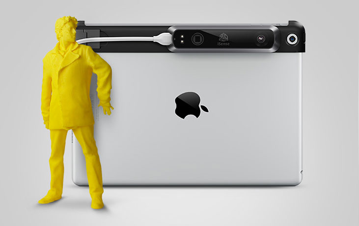
Using the Kinect and Skanect Sofware to 3D scan is a really fun thing! I first saw that in New York at the Makerfaire and I was then impressed by the way we can use common things in our sets of toys to recreate images. Faces are not as well rendered as using an iSense from 3D 3DSystems. This scanner is made for an Iphone or an Ipad and can be very portable compared to a Kinect, which needs not only a laptop but if using with Scannect, a specific video card. See the system requirement here. I also seen it at the Makerfaire New York and hope to be able to play with it soon.
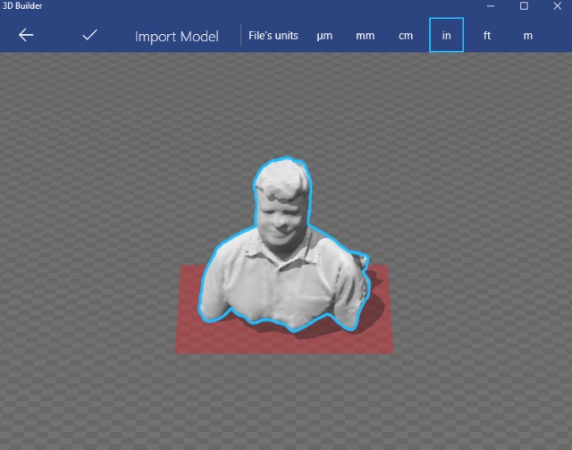
Results
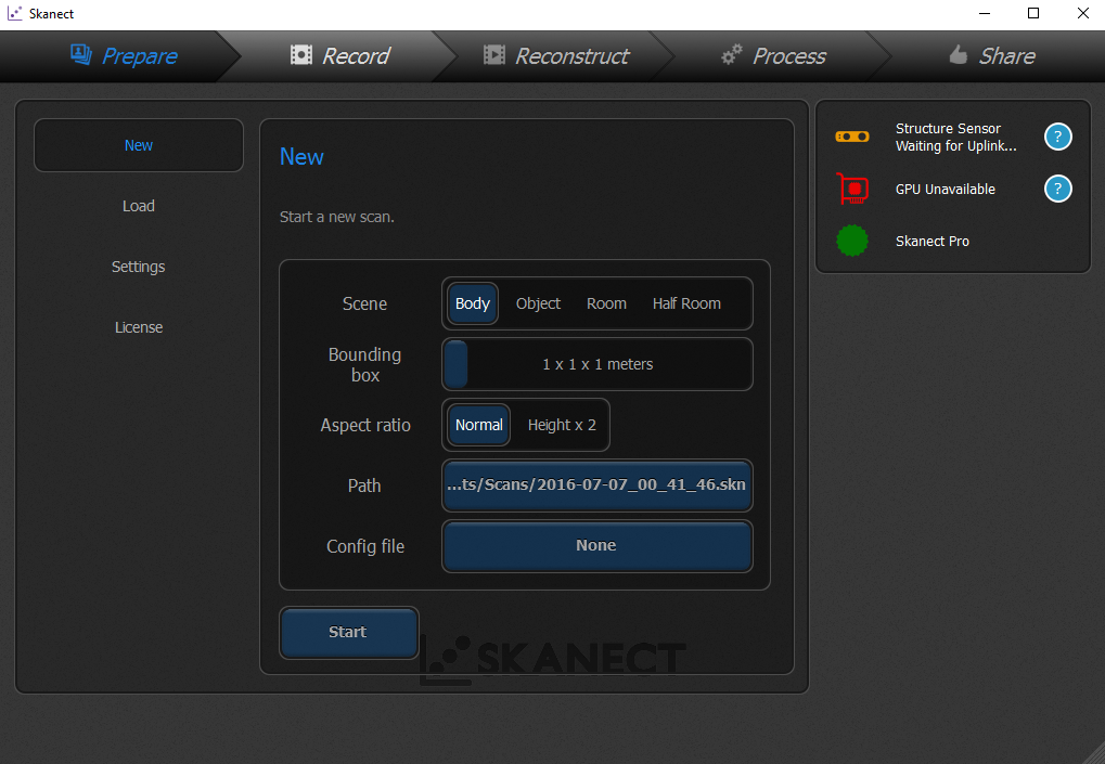
The steps to make this was really straight forward, which are :prepare, record, reconstruct, process and export (share). The only thing I would have to say is to make sure the scan objects are Watertight if it is for printing, you can always use a software such as Netfab to fix in post production. Otherwise it will not print properly or not at all.
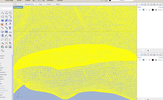
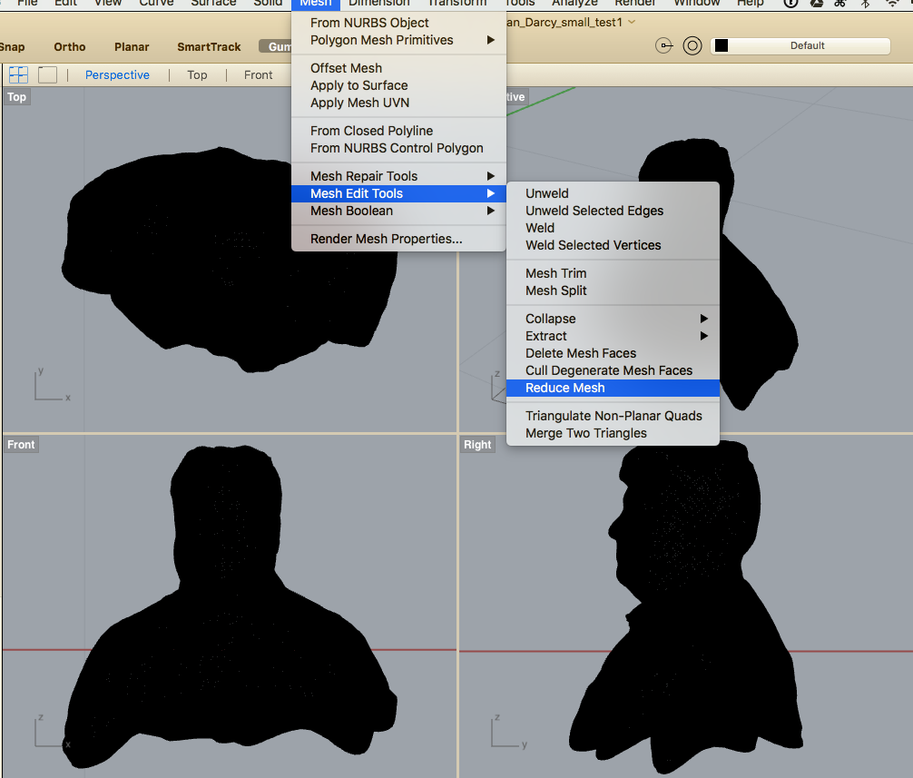
Reducing file size in Rhino
Note that the stl file generated with the export with Skanect were more than 40mb and I had to use a 3D software to reduce the number of meshes and it still gave me a 10mb file size. I made an output with to much detail in Scanect thinking the result would be better. My guess is that if I had a turn table with something to hold my Kinect and keep it staple while scanning I will have a better result even if the number of meshes are lower because they woulds have been more accurate to start off with. Hypothese to be answer in a next exercice!