output devices
Input wind...Output Awesome.
Anthony Howe's Kinetic Wind Sculptures Pulse And Hypnotize
Note: My code and files and a lot of photos can be found here in the Week 13, " Week 13, Output" folder. I am only posting low resolution photos on this page. Week 13, Outputs
Stepper Motor
For my output assignment, after talking with my guru, we decided that I should try getting a stepper motor to run. This would be helpful with my final project sculpture and moving parts after recieving light input.
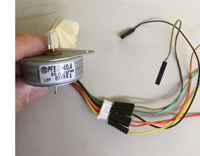
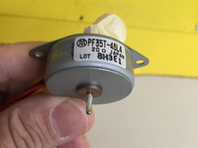
I ordered two Mabuchi Model PF35T-48L4 stepper motors.
The Stepper Motors Schematic can be found here.
I first went here to do my research on stepper motors.This was a great introduction to Stepper Motors and what they do well. If you scroll down past the Stepper Motor Models there is some very good stuff on Stepper Motor Basics.
I then went to the 2016 class archive and looked at the stepper motor section.You have to scroll a long way down to get to the stepper motor page.
I looked at Neil's board and parts picture to get an idea of how my board should be built. The only part I was really confused about was the mosfet transistors. They were marked 20 volts, but I did not know what amperage to use. We had them in 1 amp and 2 amp models. After discussing I went with the 2 amp model on my board.
Being new to the electronics world I did not know there were several types of Mosfet Transistors, N and P. The question I should have been asking is not what amperage they were, but what type. I blindly chose correctly, but they are "N" type. As clearly marked on the brd layout. I just didnt understand what that meant. Now I know that current flows in the opposite direction on a type "P" mosfet transistor.
Here is a pic of Neil's Brd.
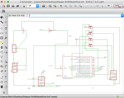
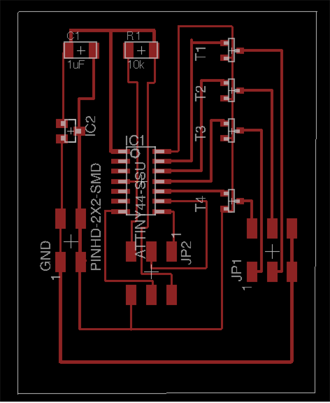
Here is my Eagle schematic.
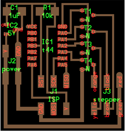
Here is my Eagle brd layout.
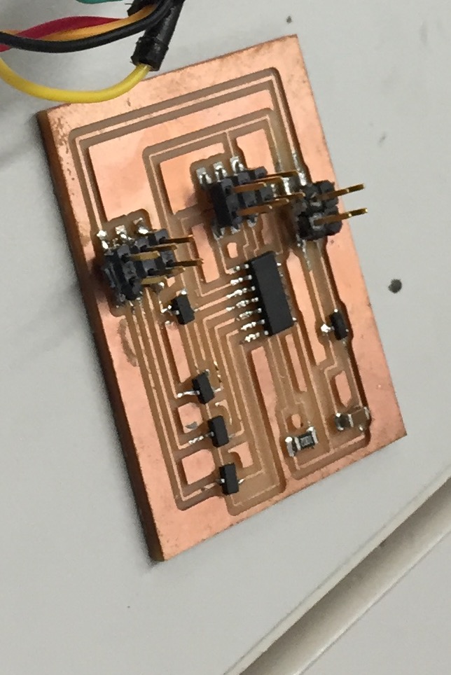
Here is a pic of my soldered brd waiting programing.
Programming the Board.
I went to past archived classes to research how to program my board using my ATTiny 44 processor. I was going to try and use Neil's C code and then translate to the Arduino setting where getting the pins correct is critical.While research past Fab Academy students who did steppers I discovered Davide Prete's 2014 Fab Academy page. Week 12, Outputs
His page did a great job of walking me through how he programmed his board. I was interested because he was using both a ATTiny 44 and an Arduino. Two things that I would be using in this endeavor.
I started by going back to the Stepper Motor section on this Fabacademys output schedule and downloading Neil's code. At first I had a hard time finding his C code because of the label. It was under FULL file. I was looking for it to be labeled C.
Neils Unipolar C fullNow I had the code and the make file for my board. The make file can be found here.
Neil' s Unipolar full make fileOnce I got it running I could modify it and get it going with my sculpture.
Programming my board with C would be more daunting than I had imagined. I tried soldering two different boards and multiple programs to try and program my board in C. At the end of the day, I could get none working and would end up having to build a fabduino to get my board programmed and my stepper motor running.
The first program I tried was WinAVR. I was advised by my teammate to do a WinAVR tutorial which can be found here..
I wasn't writing code so the most pertinent information came around the 8 minute mark.
I followed the tutorial.
1. I cut and pasted Neil's Full code into Win Programmer's notepad.
2. I created a folder named Stepper and the make and program file can be found here
Stepper Folder3. As the video instructed I created the Make file in a program called Mfile. I used the one already there, but I should have uploaded Neil's make code. I think this is one of my biggest errors occured.
4. I changed the programmer's name in Mfile to usbtiny to match my programmer and changed the port to usb.
5. I then saved the file as main.c, as the tutorial instructed, in the Stepper Folder I had created.
6. I then selected all and it came back full of errors. Obviously I was doing a whole lot wrong, so I consulted my Guru to help with my programming problem.
Together we spent many hours trying to get the board to work. The biggest problem we had was just getting the programmer to recognize the board.
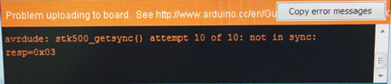
The possibilities for this error were almost infinite. Bad Soldering, bad make file, bad connections, bad power source, bricked chip etc....
Programming the Stepper with an Arduino/ Fabduino
With time getting eaten up, I decided to move on to making a Fabduino that would be controlling my Stepper Motor. I would be using a fabduino for my final sculpture.
I went back to old Fab Academy classes to find more information on Stepper motors in an Arduino envirionment. Both Davide Prete '14 and Sigga Helga '15 had good information on thier sites about Stepper Motors.
Sigga HelgaSigga Helga had a wire color Pin schematic that I looked at. My global instructor also told me that "Stepper motor wire colors are not all the same and might do different things. Always refer to their data sheets!"
If we couldnt find the data sheet we tested the wires with a voltmeter to decern pairings of wires. If the circuit was completed then we could pair the wires togther and work out the wiring to Arduino pins. The stepper I used for my Sculpture, I salvaged from an old polar 3-d printer. It had no labeling or identification and was able to get it working like this.
I also consulted Davide Prete's page again, as he had a very nice wiring schematic shown below.
Wiring Schematic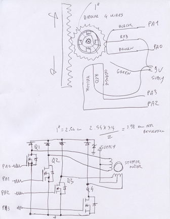
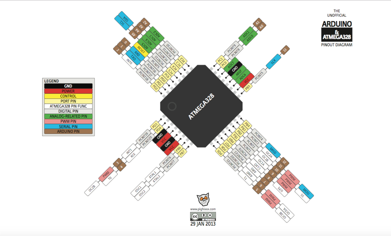
I then consulted the pinout for the ATmega328p chip that our Fabduino's would be running. Its pinout schematic is shown below.
I was able to connect the Stepper to the Arduino and program it.
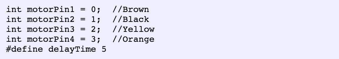
Here is a screen shot of part of the Arduino code
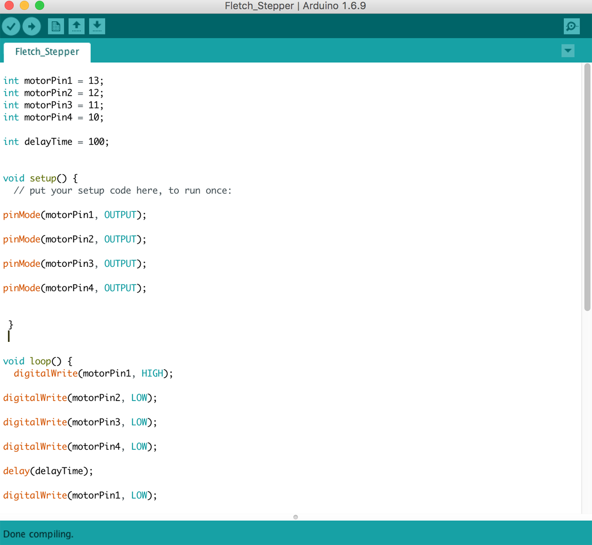
The whole code can be found here.I know that I will have to modify it quite a bit to work with my sculpture.
Week 13, OutputsI was able to get the stepper motor running from an Arduino, so I was confident I could get it going on a fabduino. Here is the video of my stepper running on an Arduino
The next step was to fabricate a Fabduino to run the stepper with the same Arduino code.
Our lab started to make a satshakit Arduino. It can be found here.
Satshakit ArduinoWe modified it a little and added an extra ground pin. But is essentially the same. Below is the schematic and board.
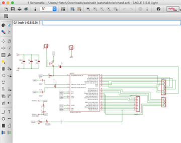
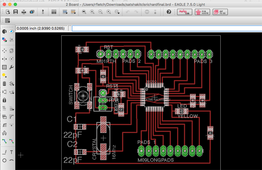
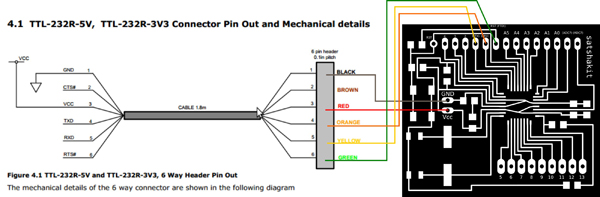
Above is the wiring schematic used to program the Satshakit Arduino using a FTDI. The process is found on on the link here, under the Getting Started Section
Satshakit ArduinoI used the same program and I had used with the arduino. It ran, but not well, really jerky and didnt look like it was executing the code.
Here is the fabduino running the stepper, poorly.
I was not happy with the way the stepper motor was running, it was running poorly and just making jerky motions back and forth. This is not what should be happening.
I knew I had to get this running, but was at a roadblock. I needed to try something else. With assistance from former fab graduate Adam Harris I got it running.
The problem was with the mosfet transistors. On the Fabduino I was bybassing them so the code was not getting executed properly by the stepper motor. I needed to use a breakout board with mosfets to properly engage the coils in the motor.
1. The first thing I did was go back and rip out the ATTiny 44 board and everything else but the jumpers for faduino communication and headers for the Stepper.
2. I then soldered the mosfet connections corresponding to the old chip pads and jumped them to the correct fabduino pins. This was by far the most difficult soldering I have done. The Attiny 44 chip pads are small and getting a soldered connection with a group of tiny wires without touching another pad was difficult. After considerable time I was able to accomplish the task.
I picture of what I ripped out and jumped is pictured below.
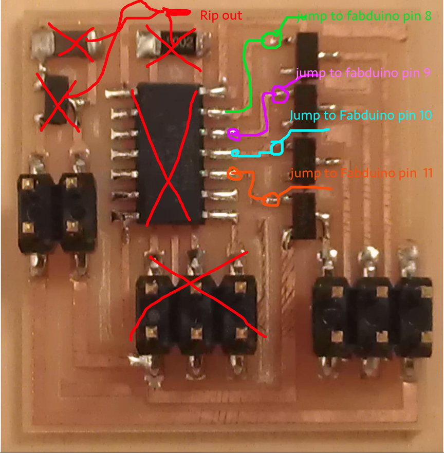
I then used a simple stepper code from the Arduino Library and assigned pins, 8,9,10,11,to the motor wires. Below is a screenshot of the code. We then programmed the Arduino using a FTDI, following the steps on the Satshakit Arduino page
Satshakit ArduinoThe process is found on on the link here, under the Getting Started Section
Short term success, but not what I needed for my final project.
While I was excited to get the stepper running and working I later realized that the six wire small stepper motor I had chosen was not going to be strong enough to provide enough torque for my sculpture. I was hoping to scaffold these lessons into my final project, but it appeared that this motor was not going to do the trick. I would have to order a new stepper or find one that was more powerful to run my sculpture.