
"Grue", by Qannik, off the 1001 games you must play before you die page found here. Zork
Note: My code and files can be found here in the Week 11, Input Folder . I am only posting low resolution photos on this page. Week 11,input devices, The Grue
Input devices
My Plan
This week my plan was to learn to code my board to be a light sensor. I want my final creature sculpture to light up when the room gets dark. I was inspired by a game called "Zork" I played as a teen. In the game, if you traveled in the dark you were likely to be eaten by a Grue (a mythical monster that lives in the darkness). I was lucky in that one of my teammates also was doing light sensor and he was able to help me with some of the code. The board design inspiration, I would take from the Fablab Archive.
The Board
The first thing I did was go to the fab academy Archive and look at the files for light sensing boards.
It can be found here. Fab Academy Light Input
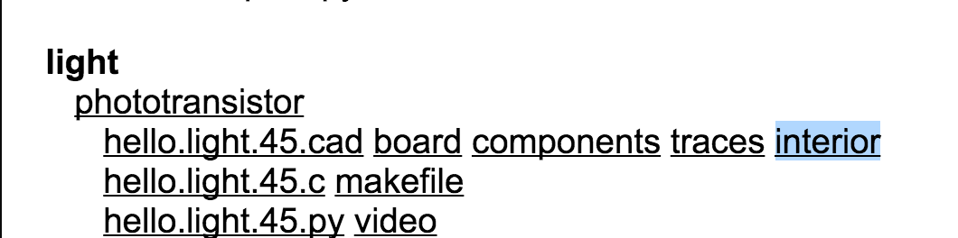
The Board I chose from the
The pictures above shows the choice of interior to get the G-Code, so our other mill could mill out the circuit board. This was the first time I had milled from G-Code and Tom told me that there we just hard to change the profile to make sure it did not mill through the entire board. After doing that it milled great. After milling , I then soldered the parts in it and it came out perfectly
Because I was not ready to program the board yet my classmate David Taylor took then programmed the board with an arduino programmer to change text to vary upon different light stimulus.
I thought I understood the concepts enough and was now ready to build my board and code. it. I took the parts list from Neil's board.
Parts List
1. ATtiny 45
2. Photosensor
3. 1 uf cap
4. 499 resistor
5. 10k resistor
6. 6 pin FTDI header
7. 6 pin ISP jumper
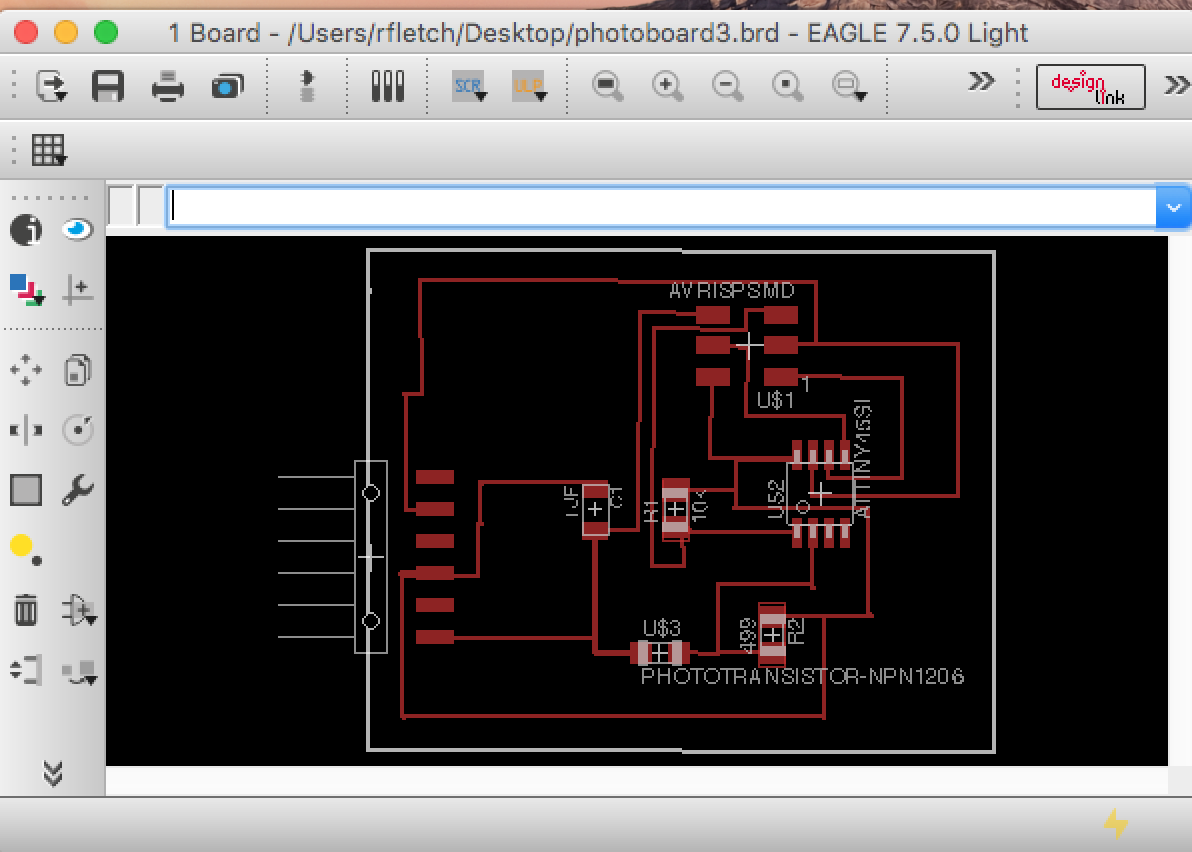
Here is a picture of my board design.
I was able to peace together what connected to what from Neil's design. Labeling and naming things in Eagle was much easier after the many boards I had designed earlier in the class.
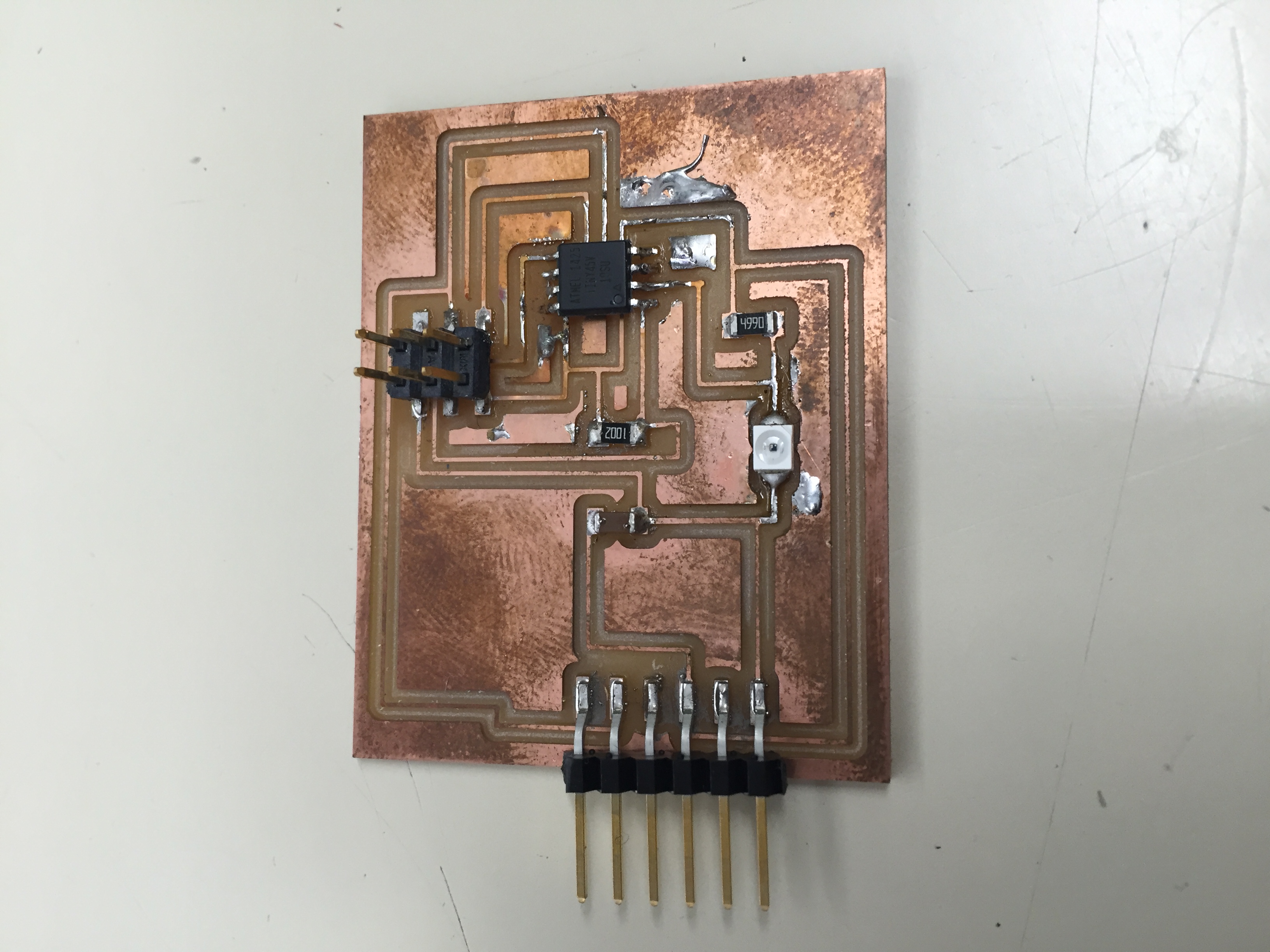
I had one issue where the mill did not cut a trace
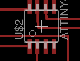
The line right above the lower pins on the ATTiny was too close, so I had to cut it with an exacto. I later went in and changed the design so it would cut properly
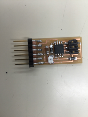
Here is a picture of my finished board cut and soldered.
Now I was ready to put in code.
Coding
When David coded his board he was really good about showing me what he was doing and why. I also went to this site and did some research. Light Sensor Using Arduino
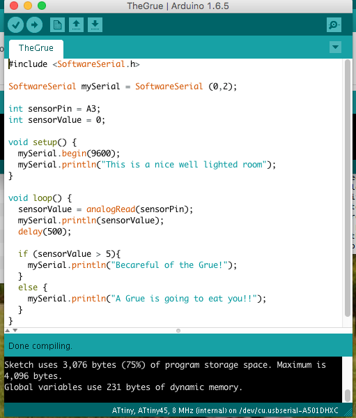
When I plugged in my board I was estatic to get a read out on my serial monitor. But I noticed a problem, when I covered the light sensor on the board, I was seeing no change in the script on my serial monitor. It should be changing as the light dipped in brightness. Something wasn't working. I did notice that I had a very low value for input. It can be seen here.
I did see a value moving Here is a screen shot of the code.
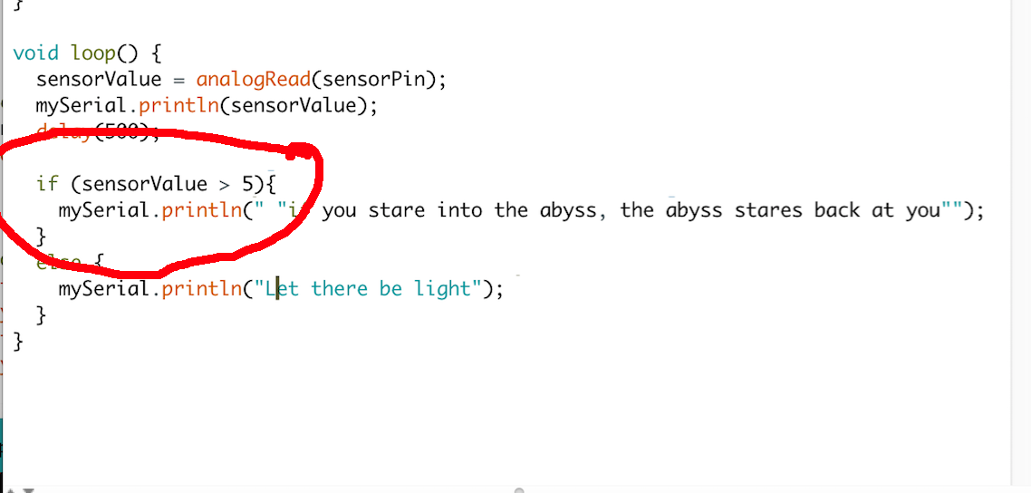
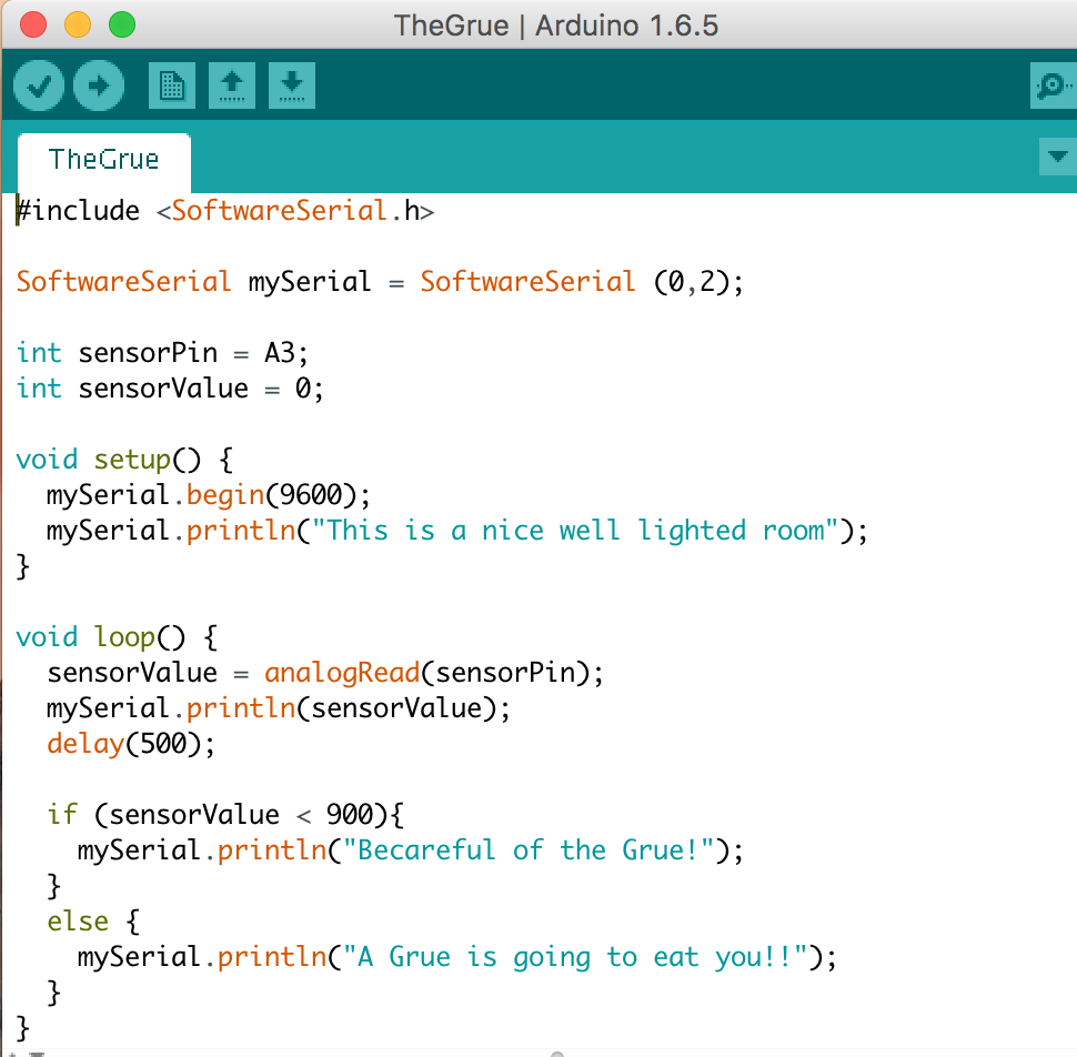
As the serial monitor was spewing out data. I tested covering the light sensor. The value on the serial monitor would go up when the light sensor was covered and down when there was light. I realized I had my "if/else statement" values way too low. They needed to be within the change that was happening on the serial monitor. Somewhere between 1100 and 600 (Tom later told me that the value spewing out on the screen must be an measure of resistnance.
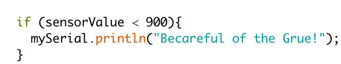
When I changed the values to 900 and the greater than symbol to a less than symbol things started working.
Here is a screen shot of the whole code. As simple as it was I am proud of it..
Here is a short video of the code working and my excitement.
Note: My code and files can be found here in the Week 11, Input Folder . I am only posting low resolution photos on this page. The Grue Arduino code