This week, we had to create a parametric press fit construction kit
In our lab, we try to identify different generic platforms and materials we can use with students and community members. I decided to try to create a simple assembly consisting of a disc with 8 slots and segment pieces with slots on each end to link them together.
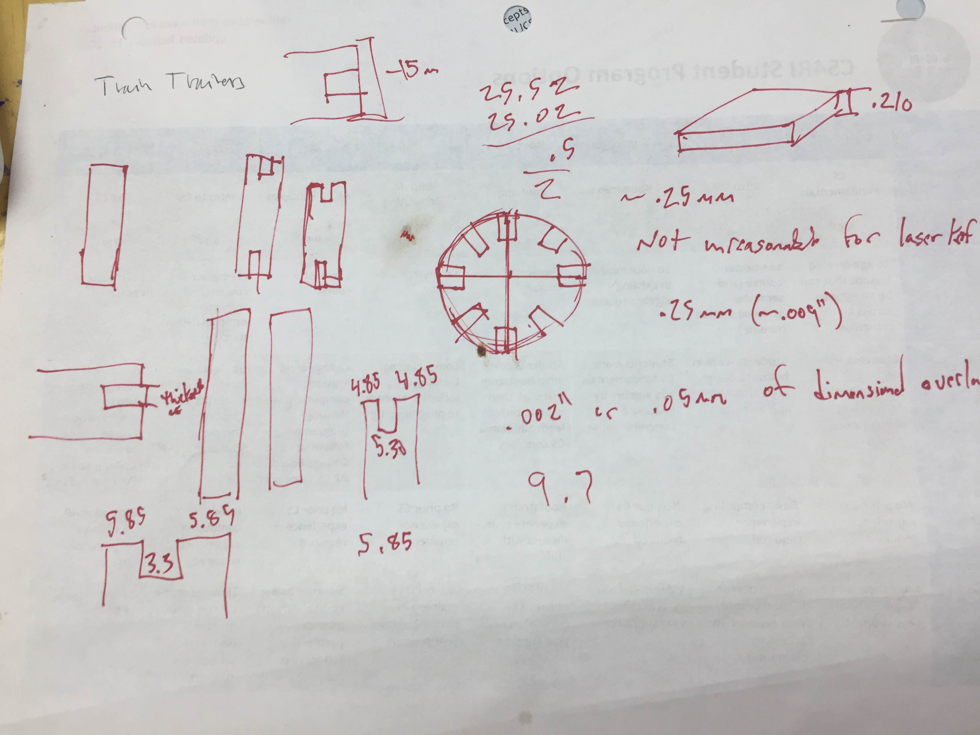
Kerf is the total width of material the laser cutter removes. In order to get a nice press fit you need to account for kerf in your design. There is an excellent tutorial here. Here was my kerf cut test.
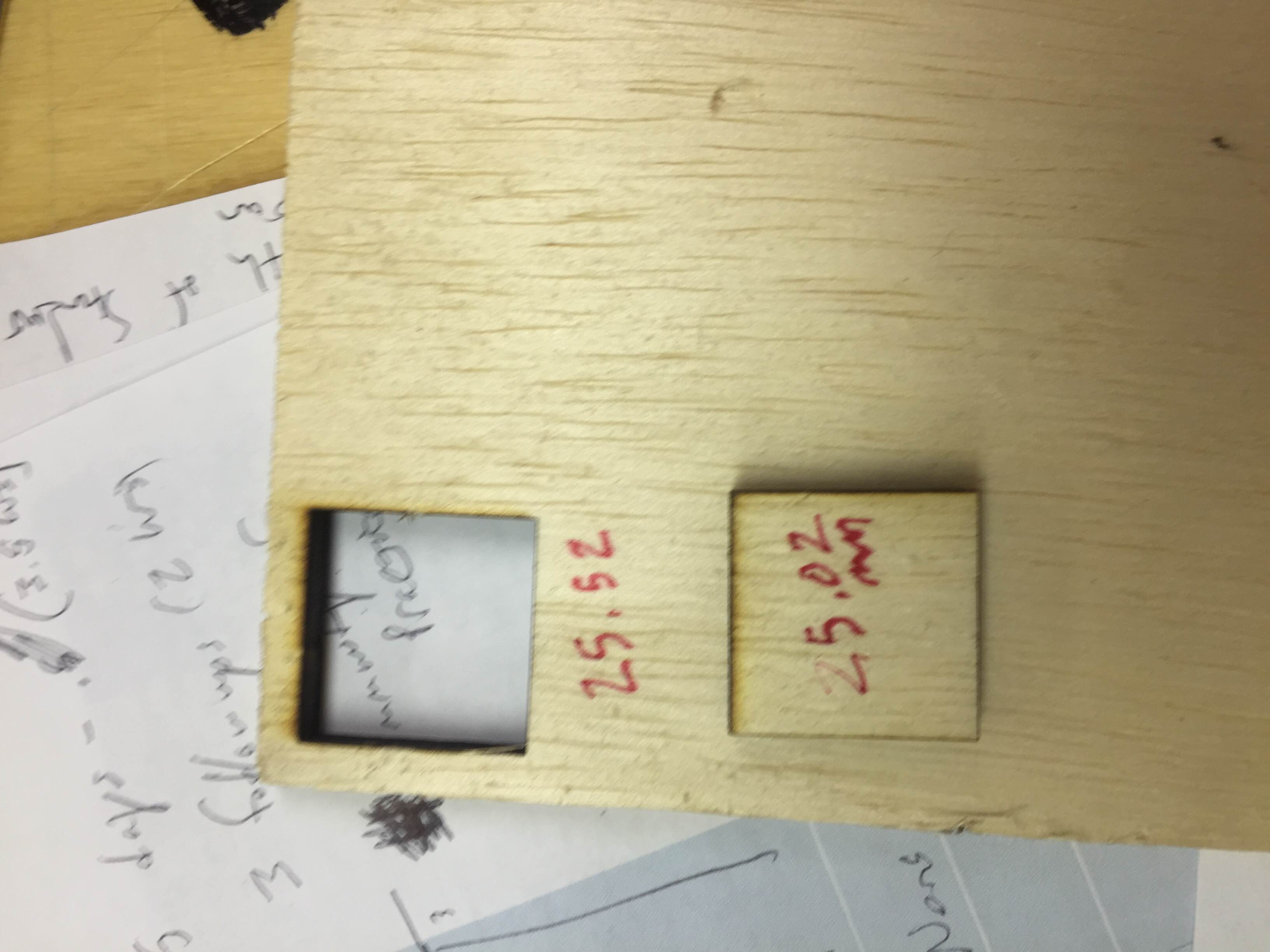
Based on the lest cut, my kerf value was ~.25mm which seems high, probably because the calipers are I use are a little sensitive. It's more likely the kerf is ~0.18. After calulcating the kerf I chose other my other dimensions and created adjustable parameters
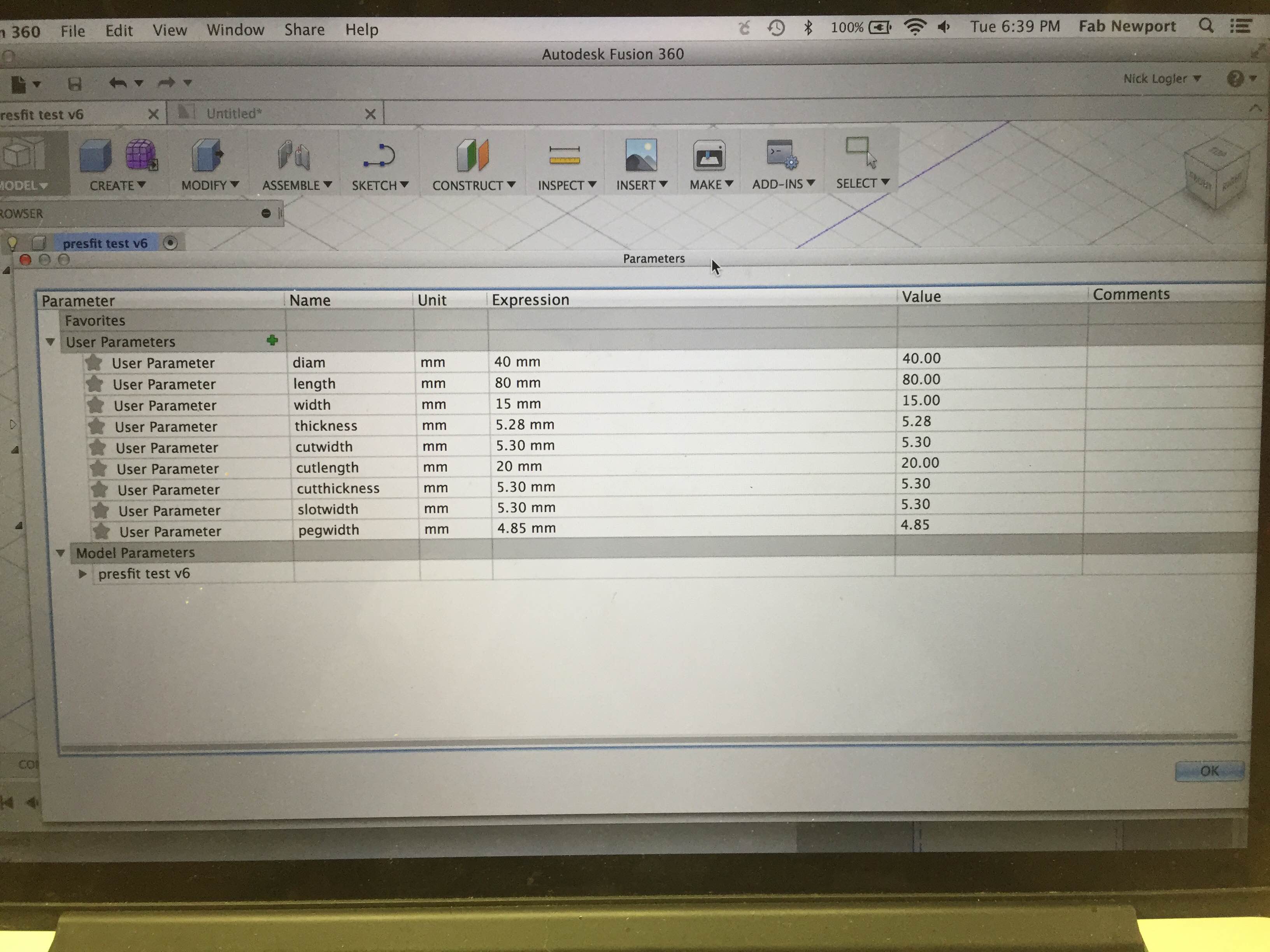
After a couple of test cuts I found some dimensions for a reasonable pressfit. It isn't perfect, so I will have to go back and adjust some of the parameters
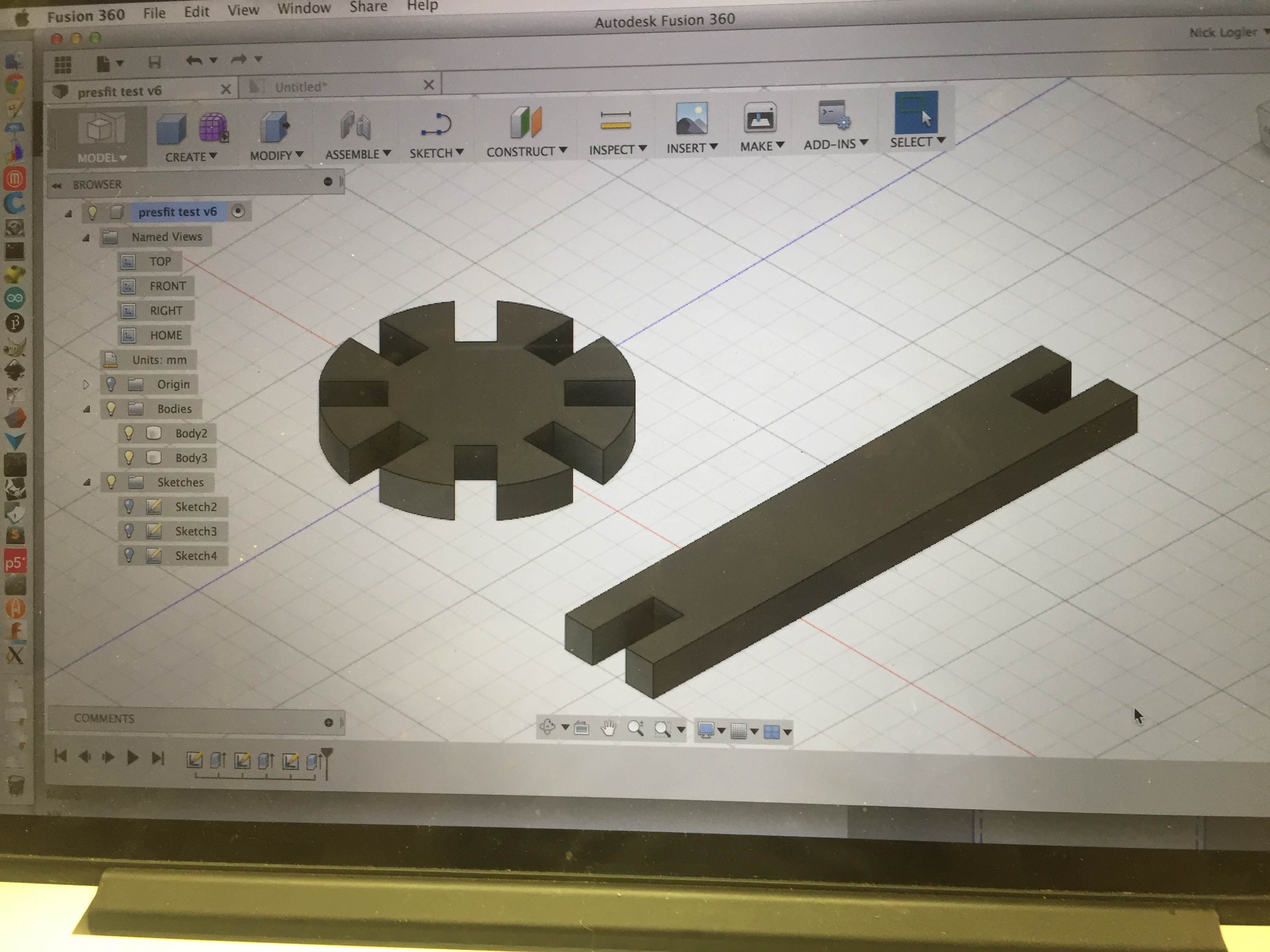
I used Autodesk 360 Fusion to render my design. Once you have 3D geometery in Fusion you can generate drawing and pdfs of your design. I'm new to Fusion so I had to wash the design through Inkscape (a 2D vector graphics program) to prepare the cut lines for the laser.
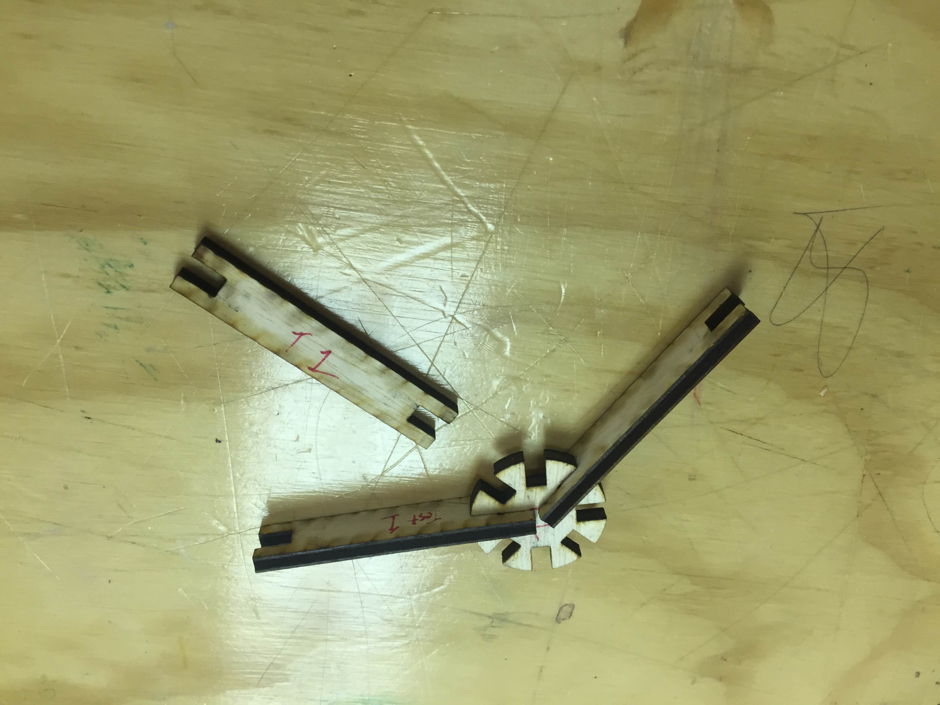
I thought I had the kerf right in the first cut, but it ended up being about a 1:1 fit. Thanks to parameters I only had to change one variable to correct it. The second cut is a solid porotype
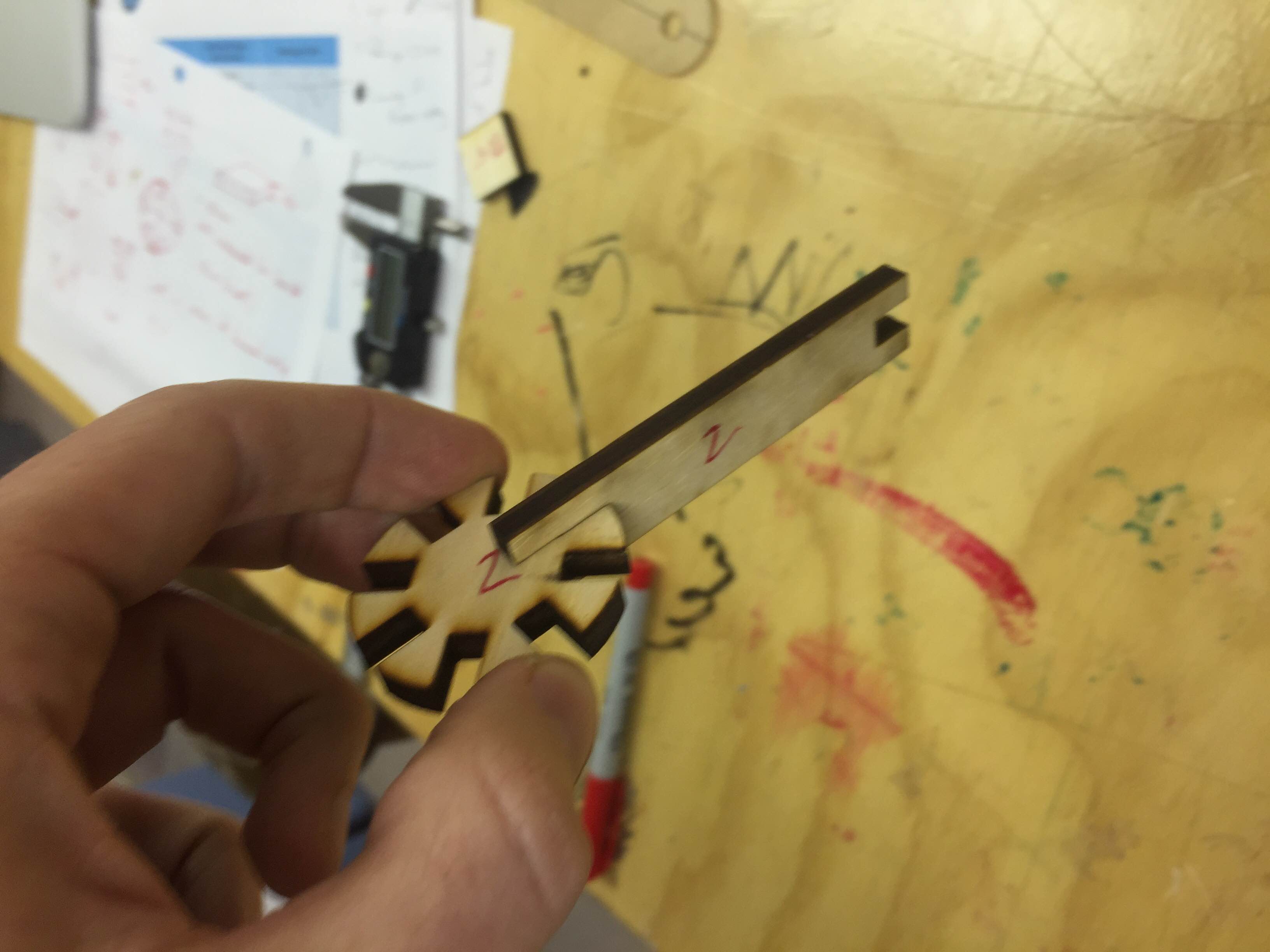

I've got a final working prototype of a generic constrcution kit I can use with students and schools that come into the lab. The press fit is solid but not perfect. I should go smaller to get it working. Other next steps: