For my project to fulfill the output devices component of the course, I am creating a relay device, which will digitally control the flow of electricity to a light source. In order to do this, I first milled a SSR board. This was the first time that I needed to make through holes on a circuit board. I created the board using Eagle and I was impressed by how well the program's files translated to the Modela milling machine, especially in regards to the size of the holes.
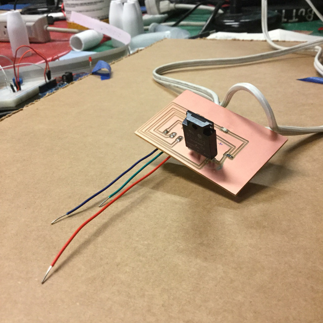
Once I had the board milled, I soldered several components in place. The relay board requires an LED, a 1K resistor, a 150 ohm resistor, an N-mosfet, a two-hole terminal block, a 3-hole terminal block, and the relay component. The relay component, and the terminal blocks fit snugly into the through-holes and so I clipped the remaining wire and soldered the ends to both sides of the board.
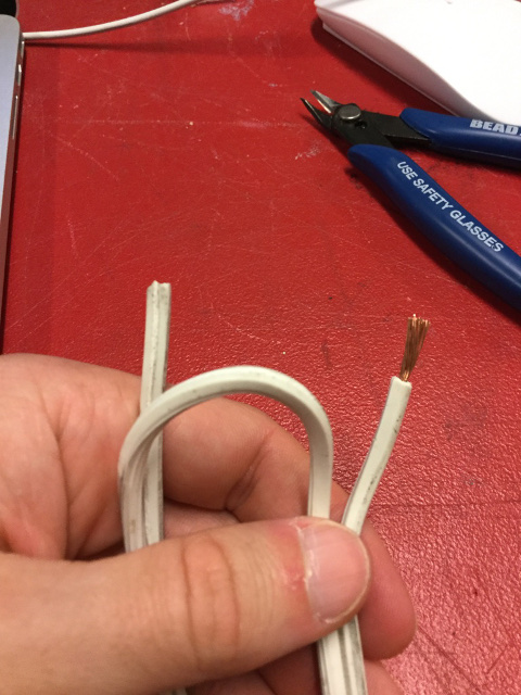
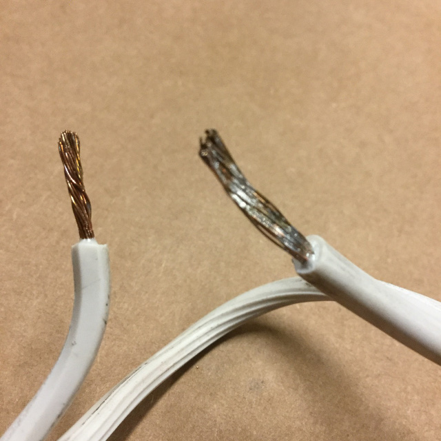
Next, I needed to work on the power supply to the lamp. I took a power cord and split it down the middle. I clipped one of the halves completely so that the wires inside were exposed, and peeled back the rubber protective layer surrounding the copper wires. I then needed to tin the wires using solder, to make sure that they stayed together when I put them into the 2-block terminal. The 2-block terminal works by inserting the wires into cavities in the dock that sit below the board. Little screws can be engaged in order to keep the wires in place and to secure the connection.
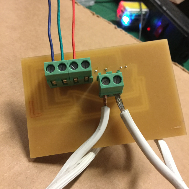
From here, I cut three smaller wires to insert into the 3-block terminal. These would later be the connection to the Fabduino. I used a red wire for power, a blue for the signal, and a green for ground. To double check that the connections were in the right place, I checked back with my schematic on Eagle.
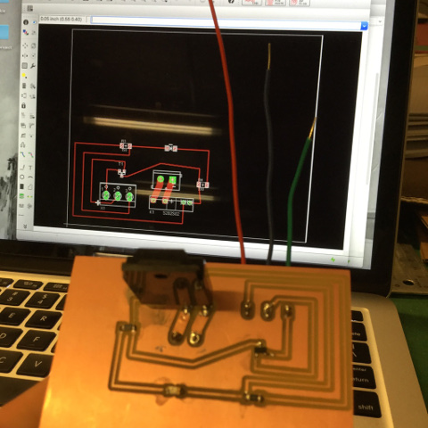
Finally, I tried to test my relay by hooking it up to the Fabduino board, which was connected to my computer. I plugged the lamp into the power cord, which was also attached to the relay board. The LED on my relay board was illuminated, showing that the connection was good. As I tried to engage the board using the Arduino software on my computer, however, I realized that something was amiss. The lamp did not change and a message popped up in the program saying that there was no USB attachment. So, it will take a little troubleshooting to work through!

In the end, I checked all of my connections and in some areas, I had not soldered the components to the traces very well. So, I spent more time securing all of the connections. As it was my first time using the through-hole connections, I did not realize how much solder I needed to make a good connection. After adding solder to all of the connections and testing with multimeter for continuity, I tried to blink the lamp again using Arduino. In the end, Shawn realized that I put the wrong resistor on the board. Once this was fixed, the lamp began to blink!
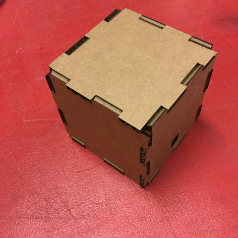
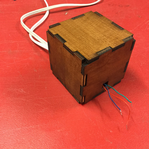
Once this was completed and I knew I no longer needed to modify my board, I decided to create a box to contain the board and wires. Since the wires can be very dangerous, this is a necessary last step. I modified the box I had created for the parametric design week to include a hole for the wires in two sides. After running a test out of cardboard, I then created the box of wood. The tight press-fit will prevent the wires from endangering anyone.
Files:
Traces Rough Board Schematic BoxCode:
Blink