I am very excited about what I have seen regarding this week's material. Shawn gave our class a demonstration of what can be done with Processing and it is incredible. It seems relatively accessible from what I have seen and seems similar to Arduino, with which I have grown more and more familiar.
A few weeks ago, I was able use my input device, a light sensor, to take a reading, which I was then able to translate as serial values that I displayed on my computer screen as a series of numbers or characters. This weeks assignment can build off of that, taking it a step further and converting that serial data into a more dynamic visual that reflects changes in the data.
In order to prepare for this, I watched a few tutorials that I found online, introducing the very basics as a refresher to Shawn's lecture. Some were more helpful than others, the most helpful was Serial 5 - Basic Processing, posted by Jeff Feddersen. In this video, they worked with Arduino and a potentiometer, which is like a dial that, in this case, controls the amount of current flowing through a circuit. The turning of the dial corresponded to a circle moving across a screen: the further the dial was turned, the further along the screen the circle would move.
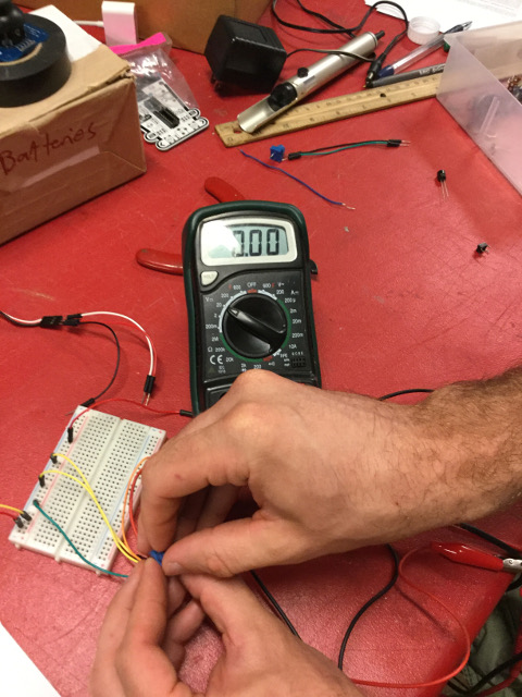
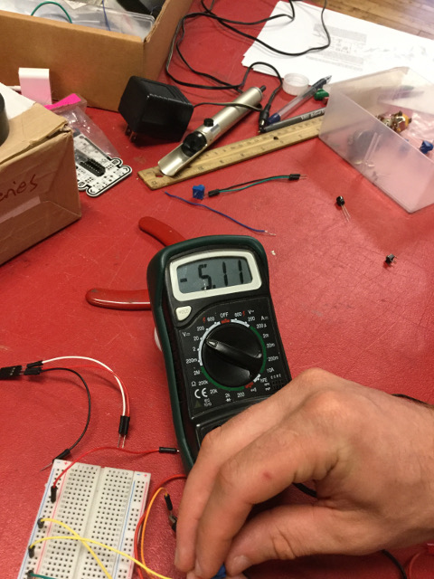
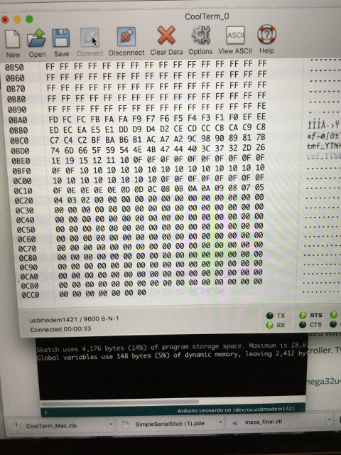
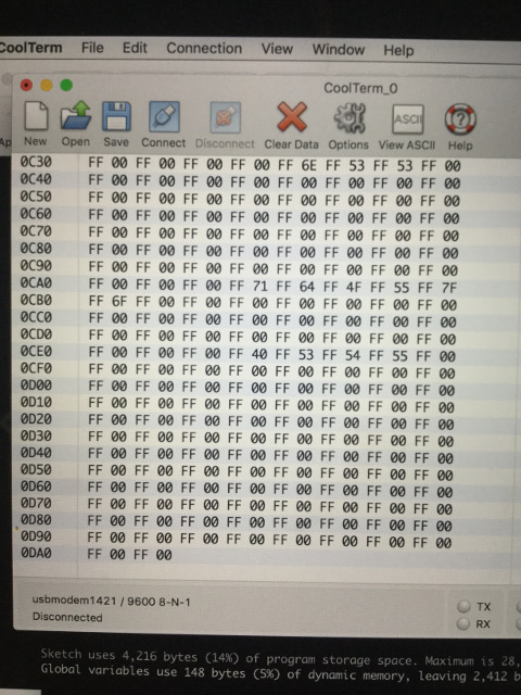
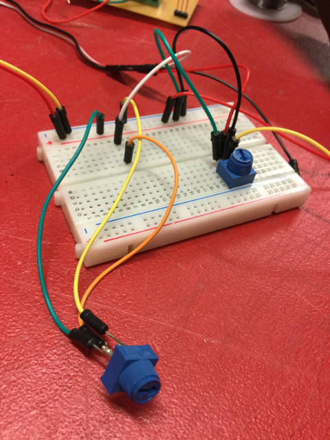
My first attempt at completing the assignment in Processing and Arduino was perhaps a bit naive. Since I had already familiarized myself with the serial monitor when working with my light sensor, I thought that perhaps I could use my light sensor with the same code that the tutorial had used with the potentiometer, but it was not so simple! After a few failed attempts to edit the lines of code to suit my light meter, I decided to work with a potentiometer. I set up a breadboard with a potentiometer, but still could not get the potentiometer to work with Processing correctly. I imagined it was the wiring of the breadboard that tripped me up, but the serial monitor in Arduino was not very helpful. In order to get a better grasp of the serial input, I downloaded a program called CoolTerm, in which I could visualize the serial input as binary, which is much easier to grasp. It was just a matter of rearranging the breadboard before I got the potentiometer to work correctly, one end of the dial registering at FF and the other around 00, representing the most and least values in binary.
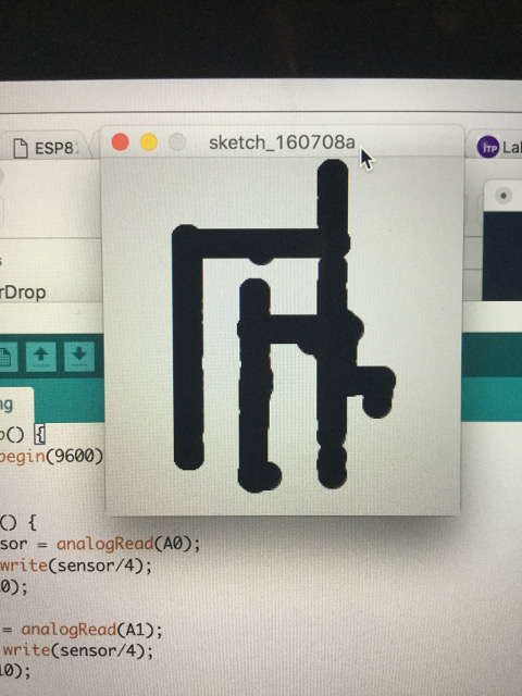
Once the potentiometer was working, I was able to execute the original code in Processing. While this felt like a big accomplishment, I needed to modify the code in order to make it my own. Shawn suggested trying to make an Etch-A-Sketch type interface that uses two potentiometers to move the circle around the screen. In order to draw with the circle, I deleted the line of code that regenerated the background as the circle moved. I also, turned the color of the circle to black. I then hooked up the second potentiometer so that one corresponded to the X position of the circle, while the other corresponded to the Y position. Similar to the example given in the tutorial, the serial was alternating from one potentiometer and then the next, so my code reads the values if there is more than one, assigning the first to the X position and the second as the Y position. This proved to make a digital Etch-A-Sketch of sorts! I cannot wait to build off of what I've already learned.
Files For EtchASketch
Processing