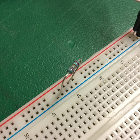
This week's assignment focuses on input devices. As I have a future project in mind that will utilize a light sensor, I decided to use one for my input device. The light sensor that I decided to use was the AMBI, which is made by Modern Device. Modern Device is located here at the AS220 Industries, and so this was most convenient. After reading about the sensor on their website, I was confident in the decision. I was also able to gather the specs needed to use the component properly. The specs call for an 50K resistor, besides the 50K resistor already built in, if it is to be used in very dark places.
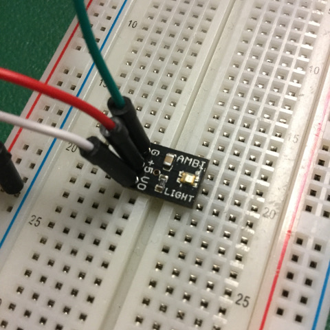
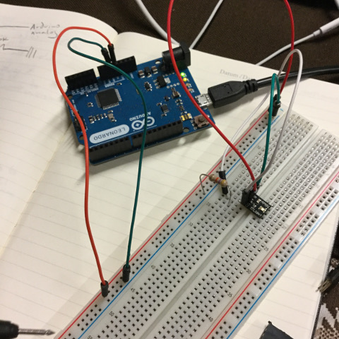
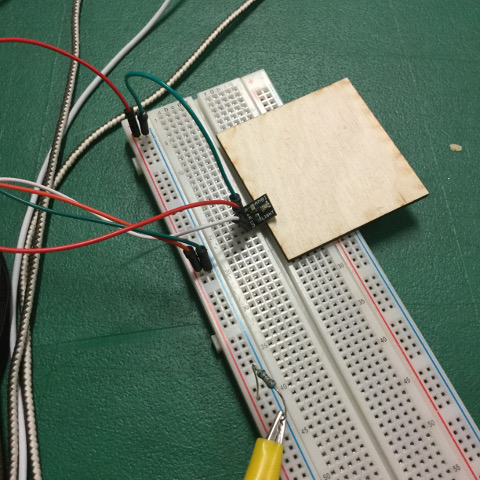
I decided to use a breadboard and Arduino in order to get the sensor working. First, I ran a red wire from the Arduino to the voltage in side of the bread board, shown as +, and conversely, a green wire to the ground side of the breadboard, shown as -. Once these were in place, I ran another red wire from the same voltage in row to the +5v through-hole of the AMBI board. A green wire connected the ground row with the ground through-hole of the AMBI board. Finally, a white wire was used to connect the VO, or voltage output, through-hole of the AMBI board to a sensor that reads voltage output.
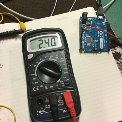
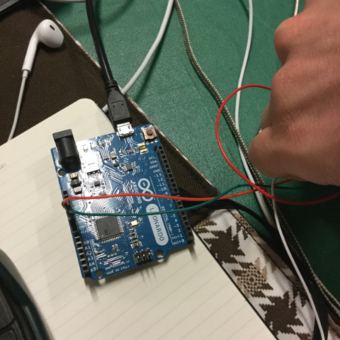
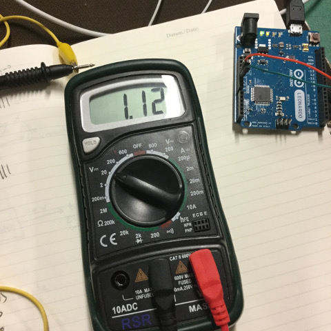
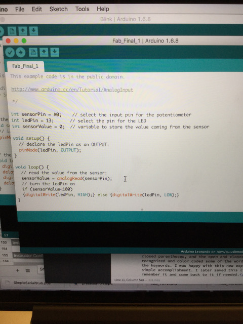
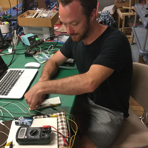
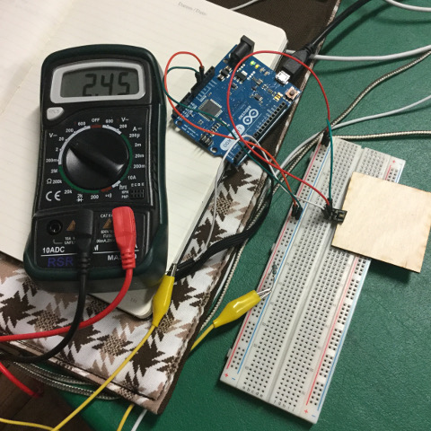
After plugging the Arduino into my computer and making sure the power was running, I tried to take a reading of the current. The connections were not secured by solder and so I had to use a slight bit of pressure to maintain a consistent connection between the wires and the breadboard. Once this was achieved, the reading of the light sensor on the reader was at 2.45 when the voltage of the reader was at 200V. After I put my finger on the light sensor, the reading was reduced to 1.12, which showed that the light sensor was indeed working. I had my friend Larry turn the lights off in the room and the sensor read 0.00, which also confirmed the accuracy of the sensor. The next step was to then design a board in Eagle that will support this sensor, which I did as part of my final project, in which I combined the light sensor with an SSR relay device. The files for that project can be found below, along with the code used to program the board.
Files for SSR relay board with light sensor
Traces Rough Board SchematicCode for Final Project