For my final project, I decided to follow through with my original idea of making a frame with a backlighting for works on paper, that will become activated when the light in the surrounding environment becomes dim. This project combines knowledge from several sections that I have covered in my Fab Academy experience. In short, the planning for this project required 2D and 3D design skills; the creation of the circuit board required knowledge of the Eagle design program and the Modela milling machine, which I used to mill the board. I soldered different components onto the board, including a sensor, for which a knowledge of input devices was necessary, and a relay device, which utlized my knowledge of output devices. Finally, the frame itself requires use of the CNC router and press-fit design.
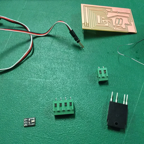
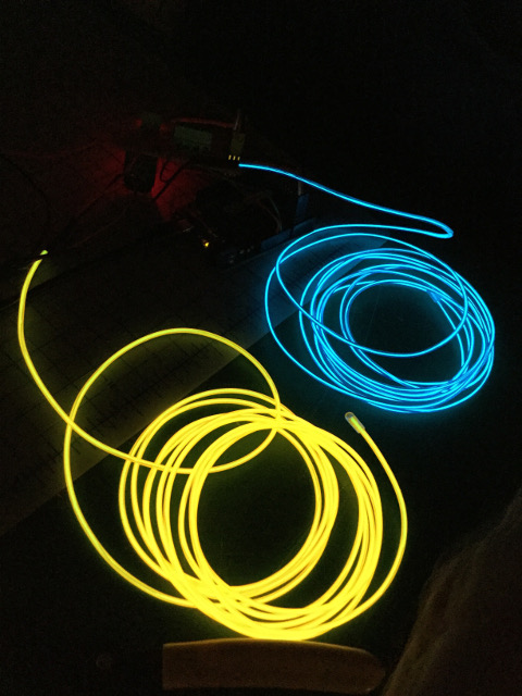
The first steps in making this project were to plan the project out fully. Originally, my intention was to utilize electroconductive screenprinting ink as a way to illuminate my prints from behind. Unfortunately, the electroconductive ink is shipped from the UK and takes about 3 weeks to be delivered. As an alternative, I decided to use EL wire, which is a cord that can be illumintated. Next, I reviewed what I had learned from the sections on input and output devices, which I documented in previous weeks. Using this knowledge, I created a board that combined both the light sensor and the SSR relay device, and would be used in combination with an Arduino. The files for this board can be found below.
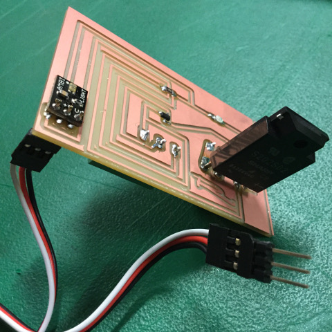
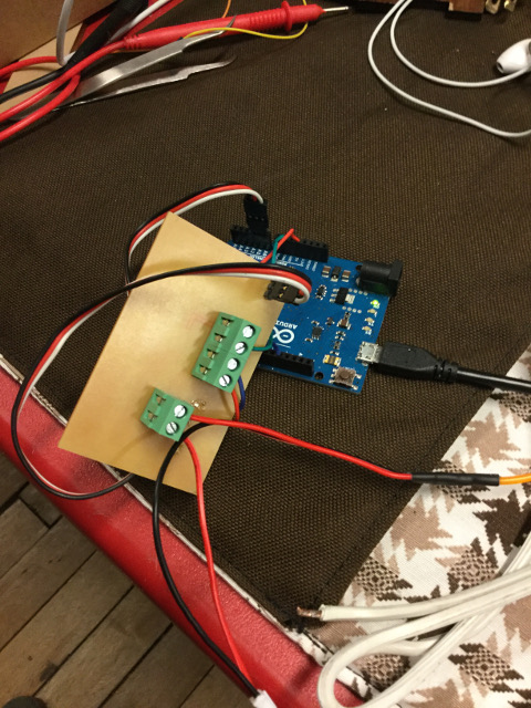
Next, I milled the board and soldered the components onto it. I connected the AMBI light sensor to the analog pins on the Arduino using a cable. I used the old cable and lamp from my first relay board for a temporary test connection, and 3 wires to connect the board to Arduino. Unfortunately, the board did not respond to Arduino, the response from the Arduino program saying that it was unable to connect. After testing the connections, I realized that the power was not making it from the wires to the traces on the top surface of the board. Shawn explained that this was a cold joint, and that I needed to reheat the solder and perhaps add a bit more. After doing this, the board began to respond by blinking the LED and lamp to which it was connected.
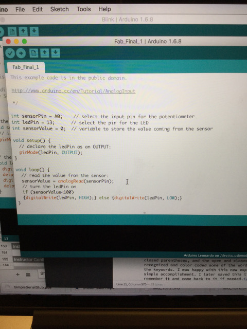
From here, I decided to use Arduino to test the light sensor. I used an Example, AnalogInOutSerial. This served its purpose and I was able get a feed of the input from the sensor. The ambient light in the room was around 400, and 0 when the light in the room was turned off. With this information, I created my own sketch in Arduino with an If/Then statement, designating that if the sensor value was less than 100, the pin will be high; else pin will be low.
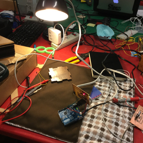
Upon programming the board in this way, nothing happened. However, once I turned off the light, an incredible strobe effect began to happen. This was because the lamp was aimed at the board, thus creating a loop that was like an endless strobe. The light was turned off, and so the lamp began to shine, which triggered the sensor and relay to turn the lamp off, which would trigger the sensor and relay to turn the lamp back on. After turning the lamp away from the board, it began to work with the intended effect.
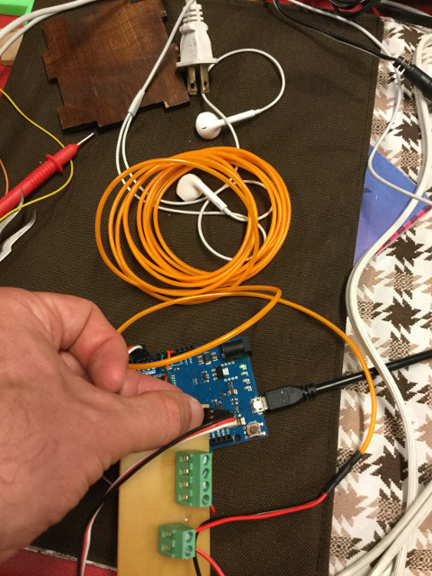
The set up worked with the cord that I had prepared for the lamp, but I next needed to make a more direct connection by using the cord from the EL wire. In order to do this, I split the red and black cords that run from the end of the EL wire. I took the red wire and cut it, trimming the protective layer back before tinning the copper below. Then I inserted each end into the two ports of the 2 block terminal and tightened them up. I reconnected the black wire of the EL cord to the 12V inverter. Fortunately, the EL wire responded in place of the lamp.
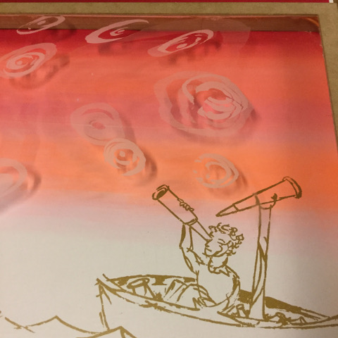
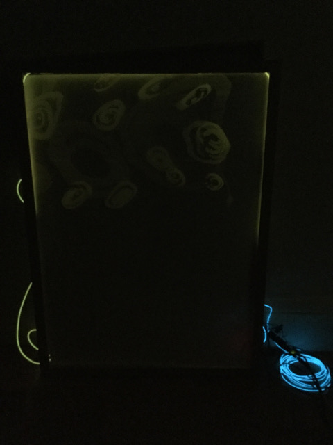
Instead of running the EL wire behind the print, I decided to laser engrave a piece of acrylic in a way that it would accentuate one of my prints. I ran the EL wire along the side of the acrylic sheet in such a way that it was hidden from the viewers' eye, but that it illuminated the engraving on the acrylic. It made for a cool effect. In the end, the board was set into the frame, with the sensor reading the light that was able to pass through the paper. This could be calibrated by adjusting the parameters of the sensor if needed. The frame works wonderfully and I am happy with the direction that it took after the unforeseen material challenges.
Files for SSR relay board with light sensor:
Traces Rough Board SchematicCode:
Sensor and Relay