
Introduction
This week we learnt about many of the possibilities available to program one's own computer interface.
We centered ourselves a little bit around Processing and Pure Data, also because what is learnt with these programs can be also transferred to other interfaces such as the arduino interface.
Assignment
The assignment was to create a computer interface that would interact with our previously made analog input devices, done some weeks ago.
Since I'm a little bit behind in terms of the week of analog input devices, I have gathered together some input devices: a potentiometer and a touch-activated slider. I also got an Arduino Leonardo that would help me by-pass for now the catching-up part. The bread board also came in very handy!
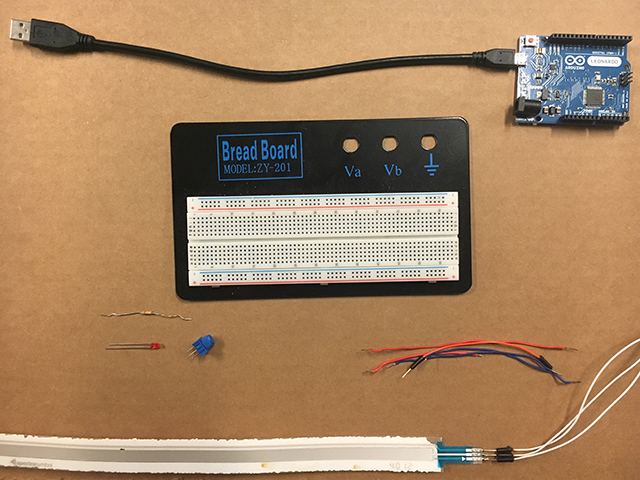
Both input devices have a ground connector, a power connector and a signal connector. All grounds and powers are connected to the same part in the bread board and then go directly to the Arduino's slots. For the touch-activated slider I needed to add a pull-up resistor that would stabilize the numbers when it wasn't been manipulated. Signals went to A0 and A1 slots in the Arduino.
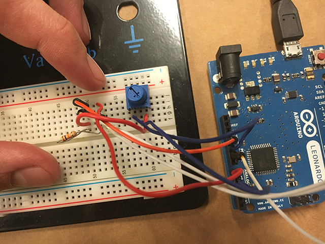
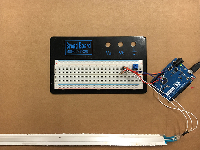
Everything then was connected to the computer and the Arduino interface helped me test and see how the signal was been sent.
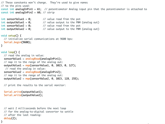
So by loading the Example file AnalogOutSerial and making some changes, I got things going. The main change was that I now needed to handle two inputs instead of one. Also, because I was sending this data through the serial port, I needed to make a difference between the data been sent by the either the potentiometer or the slider. The way I did it was by mapping one to the range of 1 to 127 and the other to the range of 128 to 255. In the image below, the output is "printLn" just to check on the Serial Monitor and see if the data being sent is correctly mapped. And it is!
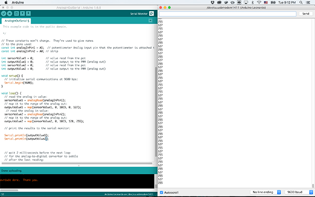
In the actual code, the "printLn" attribute is changed to "write" so that it is sent properly through the serial port.
Then it is important in the processing code to have the possibility to define TWO variables (val1) and (val2). Then, the interface has to know which one comes from the potentiometer and which one comes from the slider. This is where the mapping in the Arduino code comes in handy. There's a couple of lines by the end of the code that follow an "IF" pattern, so the condition is, if the number read is lower than 128, then it will be VAL; otherwise, it will be VAL2 (the other value). Then, towards the end, they are used as the width and the height of the ellipse.
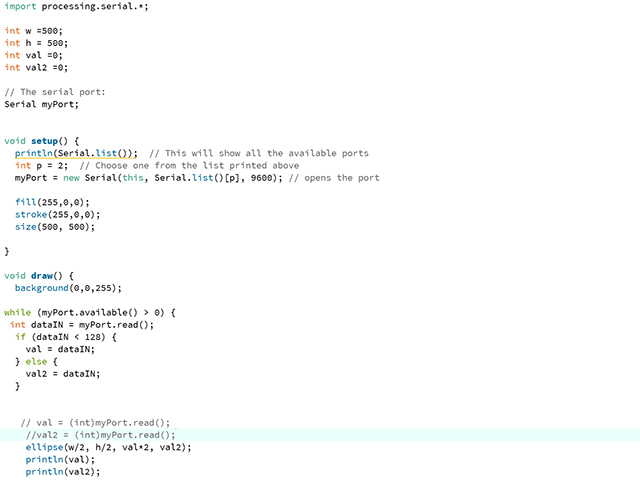
This is the interface in static, where the blue background remains as it is while the red ellipse changes its width and height depending on the values that the analog input devices send through the communication via de Arduino and the serial port.

This is the whole system working! It is very simple but I'm very happy that it works.
To proof that I can do this without commercial boards, I have done a little arrangement with the SatshaKit board, the small potentiometer board and the power board connecting the computer and running the same code. The only difference is that instead of a slider and a potentiometer I have two potentiometers in this case:
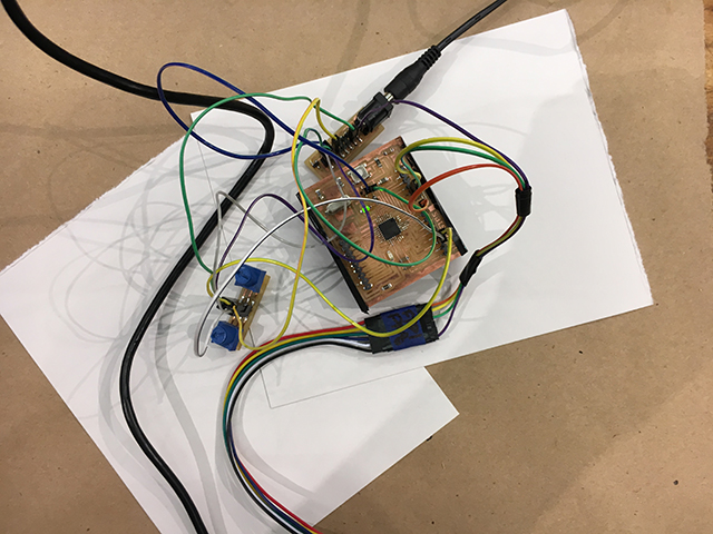
And to see the whole project functioning with these non-commercial boards, please check out this video, it's a little long, but some cool things are explained!
It has been exciting to make this work, although there is still a lot of working to be done. I need to mill my own board in orer to make this complete. But this has also helped me figure out better how to make the board for the analog input week! Updates to come...
Files
File 1: Arduino Code here
File 2: Processing Code here
To make and produce the SatshaKit board, access their deveolpment page.
To make the potentiometer board access instructions here.
To make the power board access instructions here.