
Introduction
During week 11 we learnt about input devices. Some inputs can be analog and some others can be digital. Mainly the difference is that digital inputs send a HIGH or LOW message to the microchip, whereas the analog input can send a range of values. For example, a potentiometer can send a range of values depending on the voltage that it is linked to -- 0 is connected to ground and MAX power is connected to 5V, and any point in between sends a mid-signal.
Introduction 2nd paragraph.
Assignment
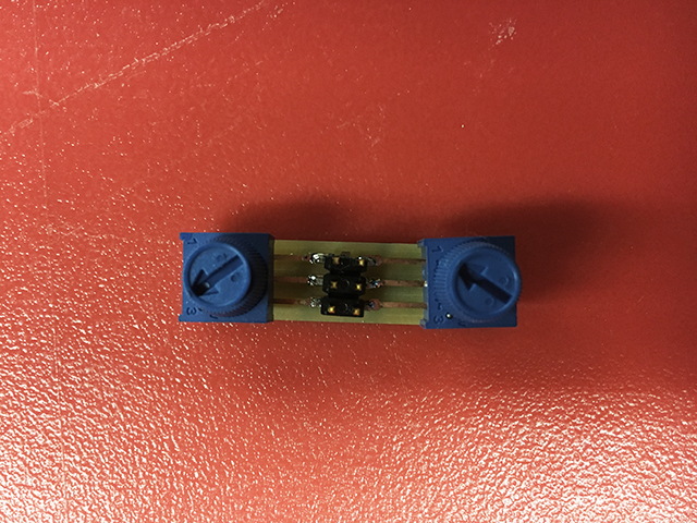
I made a very tiny potentiometer board that I connected to a SatshaKit (home-made arduino-like board) that I made. Also I had a Servo motor connected to the SatshaKit so that it would be controlled by the potentiometer. This is all part of my final project.
This is a little video of how it all works.
I milled a board with two potentiometers and each one has three pins to connect: Ground, Power and a signal. The signal goes into an analog input pin in the board.
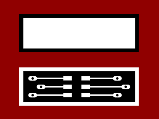
I designed the little board in Eagle and I made the traces and interior board so that I could go to the milling machine.
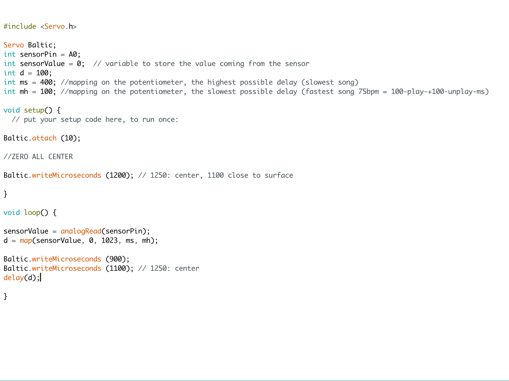
The programming of the Arduino code was pretty simple. The Servo library is included for the Output device, and then some integers are established to communicate with the potentiometer. The integer SensorPin defines where the potentiometer is attached, in this case the A0 pin. Also, the SensorValue integer establishes an initial value of 0, but will change later with the value read from the potentiometer. Another integer, d, is set to define the delay between servo operations and its initial value is 100 miliseconds. Finally, I want to have a mapping of the values that come from the potentiometer (from 0 to 1023) into an inverted range defined by the variables ms and mh.
The Setup section of the code only establishes the location of the Servo, in this case attached to pin 10.
The loop section of the code has a small part where the magic happens. The integer SensorValue reads what is coming from pin A0 and then "d" is mapped so that it goes from 400 to 100 in this case. Then the servo will go and hit the surface of the drum machine and come back, and then wait a given amount of miliseconds, given by the potentiometer.
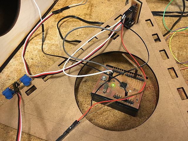
The setup with the SatshaKit board and the potentiometer board and the Servo Motor can be seen in this picture.
Working with input devices was really cool because it lets you realize how your machines can connect to the real world or receive input from users. I would really like to use in the future proximity sensors and light sensors to activate machines that I make.
Files
File 1: Arduino File here.
File 2: Eagle board here.
File 3: Eagle schematic here.